DWT

I don't think it is possible to use a calculator or laptop in the real world to "predict" accurate results. Once loaded, everything changes due to flex in the trees, stretch in the rope, and errors in the log weight estimate. I'm sure results could vary by 20% easy. This should just be used as a guidline. I would bet that taking measurments from a static load would be accurate within 4% but by then it is too late.
It seems like a waste of time to use a computer instead of looking at the system and saying "hey, we are passing 90deg of angle, we better start taking smaller pieces because of the amplified forces."

Dave
 
Dave: I disagree with your logic. Using Graeme's article as an example, he eliminated a lot of guess work by using his high-tech approach. It was much better than simple guess work based on angles. He deserves the credit for taking many factors into account. Nobody could have done it better without the technology. He did it successfully in the real world and was paid for it. To use the type of approach like Graeme's means a person better know what they're doing and be right about it.

Joe
 
Joe, I would like to see what he used to calculate the stretch in the rope and the flex of the tree. Both of which change all the angles. When we were first looking at the equations for "forces on a speedline" (way way back in time) Pete D warned me that predictions would be near impossible. I agreed with him then, I agree with him now.

Dave
 
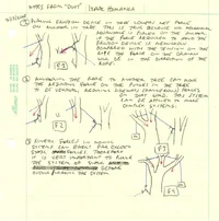
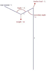
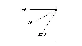
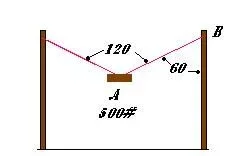
I think Dave is right, both of ya wonderful with the math, that loses me far enough back and have faith in both of you enough to figure that both paths lead to the same place. I think it is important to note, and more people take notice and try to understand the numbers you both lend. For you speak not of just figuring loads on a DWT, but; any center loaded line/sling etc. configuration. Meaning, this same lesson is the key to understanding : speedline loads, sweating in, angles on spiderleg jigs, angles on pulling a truck with 2 lines that meet in center, hoisting with crane and 2 legs of spread support, hanging a porch swing, lowering 1 load on 2 separate spread lines etc(all exactly the same numbers of angles and loads). In all cases, pulling with a single line, would carry the full load on that single line. With 2 same lines connected at same points(Prestretched the same) on support and load; will carry ½ load each; but spread apart 120deg., will each carry 1x load itself, like single line support example; from their it gits worse, more angle, increasing loads on each line above the weight above that of the load itself, on each line! That rule can stand to help, or ‘hurt’ your efforts; in the many ways above to apply the same math.

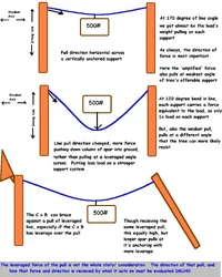
Even with the precise calculations on the angles exercise, we are guessing the strength of the supports/ interior condition of at least; then the elasticity of the line and said supports to absorb the worst part of the dynamic shock would vary, the slant to the ground of the support that caught the calculated force, the way the ropeman handled the load (running line slightly at high impact leveraged load stages of load travel, yet not building force badly, then ‘catching’ lower down at less leveraged position, but still not suddenly, then smooth on down, not stop/start until part of head touched ground or other branches etc.). Still, many variables that must be guessed at; so I maintain as Dave that we speak of patterns of guidance, for best decisions, and hard numbers as basis examples to these patterns and not everyday use. Pretty wimpy, but I guess I see room for both camps! Also, this microcosm, modular examination component by component, so that the components of a system’s patterns can be recognized, assessed individually, and how the affect each other in compounding combinations. If you can see ‘red line’ forces, leveraging on another set of leveraged forces (especially if they assess to be towards/at ‘redline’ ) ; ya know to back off, especially if those things don’t build for your favor, / cancel each other out; but rather compound against ya!

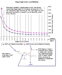
But, still, I think we should hang with the number search a little, to scout out the patterns of load and support as they drift up and from the precise measurements and become recognizable as a pattern. I think that pattern would be like on a metered scale, a feel for at what point the meter runs in the red etc.; to thumb rule decisions by; backed with the numbers we find here, confidence in superior decisions, and not letting things compound against us, but rather compound for us, by following the principals that are right here. To me, that is safety and productivity.


For those without Excel, i saved a screenshot of Dave's spreadsheet in HTML(with fake ".TXT extension/suffix that can be dropped). Dave's Excel version is a calculator that you can load different values into; here i took that and made a table of the different values from the calculator, so the effects of loading at different leveraged angles are visible, even though lacking the ability to change the numbers for the user to investigate themselves. i also added the multiplier that shows how many times the load each of the 2 supports takes on; these ratios/percentages only change with the angle, and are a key pattern i think! But all fairly from Dave's calculations, just carried on for more columns. The line tension "t" is also the load on the single legged support i believe.
 

Attachments

This guide picture to the sheet that Dave drew, seems to have to be sent seperately in this format.

You can change the load weights on the chart all day, but the percentage's of the load on each support only changes if the angle of the line changes.
 

Attachments

  • 7766-Dave's Legend for DWT Load Calculator.webp
    7766-Dave's Legend for DWT Load Calculator.webp
    7.5 KB · Views: 118
This graph that Excel produces from Dave's Calculator, shows the pattern of loading scaled out, so you can visually see where the extreme load points are, to draw own safety factors by rules of thumb.

This chart shows the support loads needed in units of the load itself. So, can that support take a pull of 4 1/2 limbs dropping the size you are gonna cut?

Direction is very important in force allways and all ways, notice that at the higher/flatter angles of DWT would pull across a tall support beam, rather than placing these large calculated forces down into the beam. Therefore, in general i think you'll find that these higher leveraged/angle pulls of DWT, speedline, spiderleg, sweating in etc.; take their increased pull and place it on the support at a more leveraged directionof pull on the support as another element; for a double whammy!

The more you drop/soften the angle/tightness of the line; the less leveraged the line's pull will be-and the less leveraged angle it will pull on support from. In trying to reinforce against worst loading range of degrees on support, set bracing pull directly opposite line angle of pull going through worst load points/degrees while lowering DWT.

On light loads, that the DWT was more to lower to a mid point than over power the load (another DWT usable element is direction control to a point with no overhead support), me ;leaning back leveraged directly against the worst line angle pull (when it happens); impacting bodyweight back at same time when load impacts + pulls with leverage +at leveraged angle on support (all at once); to balance the load more across the support alleviating the leveraged pull on the support for what i can neutralize with my efforts, has been one way. Though that is dangerous, and with these numbers you can see why i can't recomend that, but it does go to dealing with these forces and using what ya got! (Okay, even if it ain't much!)

Orrrrr something like that!
 

Attachments

  • 7770-DWT Graph.webp
    7770-DWT Graph.webp
    97.2 KB · Views: 102
In order to reproduce the points on Ken's graph:

1)Find the line tension using the dwt equations and 300 lbs. as the weight, where angle 1 and angle 2 are =. This is the lower graph and the line tension T used to calculate the upper graph.

For the upper graph:

2)Subtract either angle 1 or angle 2 from 90° to get the angle(I'll call the angle @3) the lines make with the rigging block as displayed in Ken's attachment.

Plug that angle and T into the equation:

sqrt((Tsin(@3))^2 + (Tcos(@3)+T)^2)=tension of rigging block sling

3)Divide that answer by the original load. Then, multiply that answer by 100 to get the percentage value.

Good job Ken!

Joe
 
Having read Graeme's article, seen his video, had him climb for me once, and describe the job, helped me to understand the procedure. There was very very little guess work in that most awesome of all tree jobs!!! And then there's all the other amazing stuff he does, using explosives where required, or lowering 2.5 ton 90 foot long branches, bigger than many average trees in some locales.

Dave, Ken, and Joe, thanks for the calcs and illustrations, and bringing this very pertinent subject forward in our forums.
 

Attachments

  • 7776-Record Seattle Redwood1w.webp
    7776-Record Seattle Redwood1w.webp
    65.1 KB · Views: 98
Mark: is your question getting answered? There seems to be 2 forms of the same equations available to find line tensions when the rigging point is split. 1 set of them is wrecklessly published in the TCI magazine. We needed these to look at rigging point loads. Ken posted some results using Daves' little spreadsheet.
 
Yes and no. Definitely enjoying the responses though. I like the equations and the spreadsheet. I also was happy to see the diagrams. I am going to try to examine them some more and apply some numbers.

The things that I haven't heard yet were the force it takes to lift the load added into the resultant force at the rigging points and the fact that the angles may change during lifting as well. I know that Dave mentioned the tree flex but if the tree will be hoisted from near one anchor point and then will get closer to the other during the lift, it makes it a bit more difficult to analyze where the force is during movement. There is a lot of info here, so I will look at each postition as a "static" load and go from there. Great stuff guys!
 
The lifting question would throw friction in, friction helps on hold and lower, costs on lift i think. Also, a more acute angle of DWT, takes less power to lift.


For me, Mark asking the question and Dave of "VP" (Vertical Pro insignia in avatar/picture of him) once again providing the 'engine' for the rest of the spreadsheet and graphs were key to anything i did. Joe has constantly been around to help crunch these things.

Nature is an awesome thing; giving us all kinds of options and levels of power to do many things if we can decode the patterns of forces. At some points, a few degrees make the differance, any power that we find that helps, can at some point be set agaisnt ya, and vice~versa.

These numbers, physics, geometry....whatever are key to understanding what the capabilities of a system are; and break down it's parts into components to assess, then put them together to see how they interact with each other, and then how well those assesed forces stand for or against your efforts.

This leveraged line force that is warned of, as anything else can be turned around to help if you avail yourself to it. Sweating in lines to pretighten, end of 3/1 can be anchored and line bent out at right angle for final tightening/lift etc. For as the graph and numbers show, that line pulled at angle, will have by definition more force to use than a straight linear pull from the same input effort. Sweating in is something from Brion Toss's writings, whereby shipmates that had to raise a sail and crank was broken/lost for hand winch (capstan type) to do so, they would anchor the standing end tightly and pull adjacently out on the line, that 'sneak' that line 'slack' gained past the anchor holding standing end. For them quite a slow process i'd imagine sometimes, i find it quick and easy with high return.

Pretightening a line on a rig can make all the differance in the world many times making the 'impossible' easy. Sweating in; with these bent line numbers of force portrayed can give that differance and sooner. As a climber, instead of just making sure a hitch is tight, then having ground control set line; i have the line set, then snug the hitch as i sweat the rig to pretightened. A simple change of order and purpose, maybe a second longer here and there, but real mechanichs on my side! Sometimes doing this looks a lil funny, 'falling' off a spar to impact as close to center of line as possible, with as much force as possible; so as to feed as much force into the leverage multiplier of the system, while i got it to use! According to the chart, if all i can do is get 10 degrees bend from straight line with impacting bodyweight, i leverage 5+ x whatever impacting force i input, @ 20 degree bend, i've leveraged almost 3x my input force into line; so i go in short jerks (no comment JP!); trying to pop tension up most efficiently and quickly to leveraged line.

Sometimes this takes remote sweating, so between the 2 supports i will leave a karab as sweater device and sling(s)/line as tail to sweat per load 10' away. Sometimes i throw my JP shorty lanyard (only 19') up over the line to be sweated, hook snap to sling on nearby limb, and have a 2/1 remote line sweater, that i can impact. for real high friction, but leveraged tight i form a round turn on support with remote sweater in center of lacing for sweating and removal. Can be installed from ground too.

Using a Porty i can get the line tight, stand in the sling that Porty is hitched to anchor with, and sweat line violently tight by impacting body weight backwards "falling ' from stance at porty hitch; while placing that impacted pull at a higher leveraged point on the line. For the last tightness with 5x1 compression rig, wrap pull line around porty breifly and sweat that leveraged pull into the 5x1!!!!! Just as a simple, easier slipping around Porty lacing to prusik/karab on pull into Porty line for quick <3x1, trucker's hitch type lacing, then quick sweating by wrapping pull line to Porty, then hold friction to Porty as you readjust tensioned line for lowering.

If a drawing is too small, 'feel' around the lower right hand corner of the pic for an invisible button to pop up, that enlarges the pic. Like wise, in the uper left hand corner an invisible box exists that will pop up when mouse goes over the pic. for save, print pic. etc.
 

Attachments

  • 7790-Intense Sweat.gif
    7790-Intense Sweat.gif
    377.2 KB · Views: 104
To the main topic, the decision to have wider angle on a DWT, not only increases leverage of pull on supports, then pulling using that force to pull at a more leveraged angle on the support (compounding the effect of increased leverage in line as a seperate event); but a more obtuse angle in DWT gives less 2/1 effect from the system for pretightening and support of the load. So, the 1 decision to go with a wider set angle of pull in DWT stands against you mechanically by building more leverage on line, pulling on support wrong, can't pretighten to catch as 'fast'/immediate/less shock load and less power to support load too!

Also, these numbers bare out the warning in the crane manuals about not hamering down chokers tight , to leave a more natural, 'relaxed' angle where the choker slides through itself, instead of forcing to log. These same intense , leveraged factors multiply the cranes lift against the load, running to very high forces if not let the coker adopt ~120 degree teepee at hitch point; else these same higher multipliers at the hitchpoint of sling to spar are incurred. Also, aside from the force leveraged, arching cable as lil as possible (especially under load) is best, speaking to properties of steel, as to nylon. Making the practice of hammering down a cable choker on crane jobs more than a double stop, lest these 2 independant factors (leveraged load on bend, and fragility at bend) that are scheduled to happen in the same place and time; compound their efforts to thwart me, as like the angle and leveraged pull of 170 degree DWT on a leveraged, near vertical spar.
 

Attachments

  • 7802-Dwt Pull Direction.webp
    7802-Dwt Pull Direction.webp
    117.2 KB · Views: 79
I must be missing something.
Are the angles not as described in my attachment?
A weight of 500# at 90o is 705# at the anchor.
A weight of 500# at 25o is 975# at the anchor... according to me.
crazy.gif
 

Attachments

  • 7803-angles.webp
    7803-angles.webp
    1.9 KB · Views: 82
You are right Kevin, i beleive that is the calculation for gradually putting the 2/1 pull from the 500# force on the redirect of pulley (for Dave's secondary angle "a") .

Here (in Dave's pic)the power into that 2/1 changes (therefore ruling out the 500# constant pull of your example); as the line tension "t" changes as the loaded primary angle "A" changes! So instead of holding 500# as constant load on your pic, give it the changing inputs of line tension "t" in the chart as the load lowers!

It boggled my mind as Dave had both angles changing as load lowered; but he did!

Breakthis into modules of independant machines and then leverage them against each other for the net effect i beleive! It is a lil screwy, as the load lowers, the leverage decreases on angle "A" and increases on angle "a"(that you are focusing on). Dave's spreadsheet calculates both of the leverges as the load sinks, then 'multiplys' them/their factors together as angle "A" beocomes the input leveraged force for angle "a". Compound leverage i think it would be called.

Notice also in your diagram, that pulling straight down '0' degrees would place full 2/1 power x 500 for 1000# pull on support, on a telephone pole, this wolud place that 1000# force straight down compressing the full column of the pole, non leveraged. But at 25o in your drawing/post there is 975# of force on pole, but pull is at a leveraged angle, and would put more than 1000# force if TIP for redirect is higher than 2' or so.

The numbers we been tossing around might be better understood taken from view of another direction. 2 -10' poles standing tall; tie standing end of line to top of 1, lace through pulley onground halfway between, then to pulley on on other pole, place load on ground pulley. It will take more and more effort to lift the load, the straighter line of angle you try to stretch the line to. These tensions should follow the spreadsheet. i beleive trying to hold 500# held tight on a horizontal line like this would be about infinite/theoretical force! i believe that the force would be equal for slow lowering or lifting; save for the variant friction, that would aid in hold/lower, take more effort to overcome in lifting.

If Dave's diagram was a system with the load floating, that kept a weight on the the control end floating, and no friction in the system, placing a 5# on either end should lift the other?
 
In this attachment is the 500# load greater at A with 120o or at B with 60o?
If it is 865# at B what is it at A assuming both higher attachment angles are equal at 60o?
 

Attachments

  • 7812-angles2.webp
    7812-angles2.webp
    2.9 KB · Views: 76
One point, 120o is kinda odd number to run through scenario, cuz it sets each leg on the load equal to the load; so harder to trace thru examples because of the same quanity expressed 3x(once for the load, and once on either side of the 120o legs of line under load.

i might have misunderstood your previous pic, i took the degrees to be from leg of line thru pulley to leg of line; and not just leg of line to post to produce angle?

In the scenarios we have talked about previously(with spreadsheet), there would be another leg of pull going down post at "B" to be controlled at ground(3 legs of line as opposed to the 2 legs in your pic if i read right). If the line just goes to "B" and stops(your present pic?), then the pull would be equal to the leveraged line pull created by the 120o angle at dip in loaded line.

If, the loaded line continues down "Post B"(as in Dave's legend drawing for spreadsheet/calculator); then "B" incurs extra loads of the multiplier for the 60o angle.

Otherwise the height and angle at "B" determine the leverage multiplier down "Post B", but not at the "TIP" atop "B" (that changes when 120o angle changes). The height and direction of pull on spar matter in either scenario, though a higher leveraged line pull with extra leg down the pole in Dave's scenario, the center of the 2 pulls would be at less of a leveraged angle on the spar than in your pic with lower line load! So i'd imagine that at some point in height x line pull X direction; the higher loaded line in Dave's scenario (pulling at an averaged less leverged angle of pull) would put less stress on a spar than your pix softer line pull, delivered at more leveraged angle on spar by design!

Line tension is a lot of it, that is what last paragraph in previous post is about, if lifting without friction in DWT/Dave's scenario; you would have to tighten the line up to the point of "t" line tension in be able to lift load to point where angle is "A" in line. This would put a load of "L" on spar with redirect to ground, and a load of "t" (same as line load) on the spar without redirect to ground, for that is the pull.


Orrrrrr something like that!
 
One point, 120o is kinda odd number to run through scenario, cuz it sets each leg on the load equal to the load; so harder to trace thru examples because of the same quanity expressed 3x(once for the load, and once on either side of the 120o legs of line under load.<font color="red">I agree to that. </font color>

i might have misunderstood your previous pic, i took the degrees to be from leg of line thru pulley to leg of line;<font color="red">That's what I meant. </font color>


If, the loaded line continues down "Post B"(as in Dave's legend drawing for spreadsheet/calculator); then "B" incurs extra loads of the multiplier for the 60o angle.

Otherwise the height and angle at "B" determine the leverage multiplier down "Post B", but not at the "TIP" atop "B" (that changes when 120o angle changes). The height and direction of pull on spar matter in either scenario, though a higher leveraged line pull with extra leg down the pole in Dave's scenario, the center of the 2 pulls would be at less of a leveraged angle on the spar than in your pic with lower line load! So i'd imagine that at some point in height x line pull X direction; the higher loaded line in Dave's scenario (pulling at an averaged less leverged angle of pull) would put less stress on a spar than your pix softer line pull, delivered at more leveraged angle on spar by design!<font color="red">That's what I thought. </font color>
 
"The things that I haven't heard yet were the force it takes to lift the load added into the resultant force at the rigging points and the fact that the angles may change during lifting as well. I know that Dave mentioned the tree flex but if the tree will be hoisted from near one anchor point and then will get closer to the other during the lift, it makes it a bit more difficult to analyze where the force is during movement. There is a lot of info here, so I will look at each postition as a "static" load and go from there. Great stuff guys!" -Mark Chisholm


"E=MC squared; everything is in balance, even the theory of relativity has an equals sign in the middle of it" -KC

Friction tilts things, but is inevitable in any machine. But generally start out assumming no friction, to study, just as Mark says about assuming no movement/static positions to start.
Quite failry too, support flex, lean, momentum stir in later too etc.; place the magnifying glass on one thing at a time, get the jist, then start popping the other properties in, follow a lil common sense etc.. It's part of a guess, but a pro-cedural, informed guess, a tactical plan in the end. The mentioned properties have their own domain, of possible negative, and positive effects.

If you were lowering or lifting 300#, on a spread DWT, at the 150o(Degree) mark the load on the line (and thus the load on supports) would be the ~772#. If you were lowering the load thru a Porty on the system, at 150o the line tension would be equal to the line tension lifting thru Porty with 5x1, hitting 150o mark. If at any time, you locked of on the Porty, and the angle of the line was at 150o the line tension on the Porty would be the same, the Porty wouldn't know if you had been lowering or lifting.

Because it is a point of balance, if you tension the line up or down with a fancy computer precision dial, at ~772# line tension a 300# load would sit at 150o. The given weight at a given line tension, sits at a given angle, this will be the set equality. It will work forwards or backwards (direction of force) in the system, for or against you.

Enter Friction- "Hurts"-Adds it's load (more line tension needed from 5x1 compression jig), for lifting as the friction force adds to the gravity force of the load, so it costs more effort to lift like that. Assuming the pulley/redirect at Dave's secondary Angle "a"/ Anchor Load which is Pole "B" in Kevin's was only point of friction; you would have to now raise the tension on the other side of the friction point to the ~772# + now whatever force to overcome the force of friction at the pulley/redirect. Still an equality of forces, just recognizing friction.

The 2/1 part of the DWT, is only a 2/1 at zero degrees, for there the chart shows that the required line tension is half of the load. At 120o the required line tension is equal to the load; so positive effects of DWT (aside from directional etc.) cease.

Enter Friction-"Helps"-In trade the friction force aids/reduces line tension at Porty/jig location as the friction helps fight the gravity of the load on lower and hold.

Likewise, i would think (ooops here we go....), that the load's pulley floating on the DWT line, would find balance (when no friction in pulley, branch rubbing line etc.) automatically; and ya just measure the angle; the length of the lines out of the angle wouldn't matter? i suspect Dave and Joe have formal training at some of this; spy-der just claims to be/have been a quiet watcher.

This math is not a tool to me like a hammer or saw, but a tool as a magnifying glass looking into a small open machine, to understand how to make it really 'sing' when it is closed back together; what points to glance at in the system to make quick, honest assessment.

Taking the chart and parting it out into common red, yellow, green zones of caution; might be one version of having used the magnifying glass. i think the %'s of load is the key factors to look at for one with a lil'experience. One already used to asking self if support will hold load, should be able to adjust at looking at the support in ability to support increments of the load then. So, "will that support handle 1.5 x Load and that one branch support 2.5x Load?" becomes the question.

At AS, we just talked about how 1 lil'change to climber holding their own line instead of ground control; and how it can be hard to see, but 2nd nature once ya got it. sometimes a small change can take you from the impossible to the gracefull; and or/ raise SWL of a system in the same amount of time it takes to set the system up without being tweaked.
 

Attachments

  • 7843-Leveraged Rope Zones.gif
    7843-Leveraged Rope Zones.gif
    147.8 KB · Views: 72
It is very imporant to note that forces involved in moving systems can fast outweigh (or should I say outforce) those in static systems. Does anyone have a table of values for the elasticity of common ropes? I am sure these tables are readily available on the net I am just wondering if anyone has a good site bookmarked. I am putting together a spreadsheet that will take into account shock loaded systems (very simple systmes that can be used for examples) but I need k values. :-)

I attached my chicken-scratch notes from skimming the thread. I apologize if you cannot read them, hopefully I'll compile them all into this spreadsheet once that's done.

Isaac
 

Attachments

  • 19553-IsaacsNotesfromDWTSmall.webp
    19553-IsaacsNotesfromDWTSmall.webp
    67.2 KB · Views: 77

New threads New posts

Back
Top Bottom