Video: Vertical speed line plus extras

If you're concerned about the CH sliding up you could always make a 'wrap 3-pull 2' arrangement or some variation. Or...use a cow hitch.

The only time I use timber hitches is when the load is going to be constant and in the same direction. Loading and unloading a TH can let it walk around or loosen a bit.
 
[ QUOTE ]
so Dan, do you use the clock hitch for attaching the porty to trees for lowering? How does it perform?

[/ QUOTE ]

I mostly use the cow hitch when the load is vertical. The clock hitch is most likely stronger for horizontal loads because the porty or block is anchored by two wraps of rope around the tree. One problem with the clock is that a lot of blocks will not accept two wraps of rope. Blocks use some years ago had large hooks for hanging instead of the closed block so common today. I've got 3, 3/4inch blocks designed for wire rope and they have large hooks. I don't use them for lowering but I do use them for redirects on the ground for pulling vehicles etc. and the clock works well in that application.

Even though the clock probably has a higher breaking strength than the cow the cow is a better knot when chinching up around the anchor point is of high importance IMO.
 
i beg to disagree. i'm not a fan of the clock hitch. The load is perpendicular to the line holding the device, the leveraging immense.

The more it is cinched up, the more this leveraging occurs, the looser it is, the more chance of slip.

Also, ABOK has 2 disticntly different chapters on hitches to spars. 1 chapter set for pulls perpendicular to the spar, and aseperate chapter for pulls inline with the spar.

A timber hitch is classified for pulls perpendiculr to spar, and the half hitch added to form killick would be found in the chapter for pulls pairallell / inline with spar.

Pulls with inline/ pairallell with spar are the hardest to secure soundly. Until recently, it was thought that hitching to a polished tapered spar to pull it was impossible.

John Smith developed the Icicle (same knot as the friction hitch only pulled by leg to lower coil, so that it traps the leg going to top of coil agianst the spar) to show before the Internationl Knot Tyers Guild.

On removals sometimes we give mini-Humboldt 'ears' to lay the hitching into for Porty mount, to 'defend' against upward pulls.

Finishing the timber hitch for most security, should be at a pinch at 5 o'clock in convex location i believe; relative to the inititaing pull on the device being 12 o'clock; because it is based on a backhand hitch like a cow is. Likewise non-backhand hitches (that do not stop and reverse direction), should get good pinch at convex point at 7o'clock.

Orrrrrrrrr somketin' like dat!
 
[ QUOTE ]
The load is perpendicular to the line holding the device, the leveraging immense.

[/ QUOTE ]

But Spidy the line holding the device is a circle and it's not possible to be perpendicular to a circle!

Be careful when applying straight line trigonometry to circles.

The vector angle and force calculator that Dave S. presented to us does not have a direct application when applied the forces generated within the curved legs of the clock hitch.
 

Attachments

  • 43509-CurvedVectorForces.webp
    43509-CurvedVectorForces.webp
    4.6 KB · Views: 52
Only, inline is not leveraged i think. By taking any angled/ non-linear route; we are taking more distance to carry the load; to do the same work.

Only force can overcome distance, thereby; anytime distance is altered on one side of the balance; force on the other side of the equation must be adjusted.

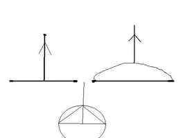
i think that the Clock, actually has 4 legs of support. But, if we plot a line from the initiating pull force on the Porty etc. straight ahead ; we will find each of these legs of support to be angled from that inline calculation of the force on the Porty(etc.).

A pendulumn will hang theoretically straight down as the minimal force position. If we pull across on the load/ weight, to make pendulumn hang at angle; we must extend the line to make the weight reach just as far down from it's support - In the Direction of Gravity (not calculating the distance of line as work done direction, looking at the direction of force flow to how far down/ not over). So, that, the angled line now takes a longer route, carrying the same load, to reach just as far down. This is just like, using a longer lever of distance travel, with same pressure down on it; it creates more force in trade for the extra distance, to do the same work of flow with the force. Inline is the shortest distance, minimal loading; all non-inline paths take a longer leveraged route.

If the teepee / partyhat of Clock is more pointed/ less blunt, then the loading can become safer, but less grip on host spar; especially noticeable on pulls pairallell with the spar; that more severely test the grip of hitches.

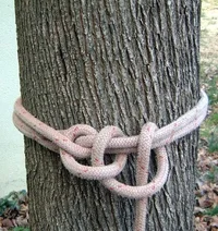
All this inline force, is also part of why on the hitches to secure, i recomend bitters seat at 6o'clock to the initiating pull on Porty; then specializing that so, that most hitches would have bitters trapped at 7 o'clock to be almost as inline pressure, only off to the side. So that the bitters would have to pull up the hill to 6o'clock and firmer pressure (if trapped at 6o'clock could more easily travel 'down the hill' to less pressure). Except for backhand hitches that reverse; then their bitters should trap at 5 o'clock. Taking clockwise wraps to initiate, Porty as 12 o'clock in all examples, any trappings of bitters or tail to bitters best at convex locations. Looking at intiiating force (Porty) pulling away from spar most, and backside seating into spar the most (to trap bitters best). Side pressures being inbetween.

At least in my 'book'....
 
And for thos reading this thread that want to see the clock hitch quickly here is the pic

43518-clockhitch.jpg
 

Attachments

  • 43518-clockhitch.webp
    43518-clockhitch.webp
    116.3 KB · Views: 28
[ QUOTE ]
[ QUOTE ]
The load is perpendicular to the line holding the device, the leveraging immense.

[/ QUOTE ]

But Spidy the line holding the device is a circle and it's not possible to be perpendicular to a circle!

Be careful when applying straight line trigonometry to circles.

The vector angle and force calculator that Dave S. presented to us does not have a direct application when applied the forces generated within the curved legs of the clock hitch.

[/ QUOTE ]
Dan,

I don't think it's so cut and dried as you're making it out to be. If you're putting a load on the circumference of a circle and its origin can be traced back through the center you are perpendicular to the tangent at that point. I believe the loading on the line would tend somewhat more toward the straight-line diagram than you'd think.
 
Yes Glen but the cow hitch is around the tree also and is exposed to the same forces and is only held by one end of the sling. The only advantage I see to the cow hitch is that is cinches up tight against the tree. This is no small advantage.

The clock hitch spreads the load over more rope.
 
But in this case (cow) the line makes a 180 around something with two leads carrying load equally away from it. Or in the case of the captured pair, they turn almost 90.
 
i think the weakness in cow is the bend maid in the standing part; except on very small mounts; i think clock bend is much greater. i imagine in theory a tensionless hitch, on proper sized mount to yield ~100% strength, with 100% eye. After that any hitch that comes around and bends that straight / loaded standing part to choke/ secure self (instead of being like tensionless hitch and using seperate mount to secure); leverages the loaded standing part; so there is percentage loss in useable tensile strength. Once again working on the imagery, that only a straight line is minimal distance; that inline/ un-arched is only unleveraged position.
 

New threads New posts

Back
Top Bottom