Training video - felling a side leaner

[ QUOTE ]
I can't believe that I wasted 5 minutes reading this thread. Can't we find more useful ways to take up this time and space?

[/ QUOTE ]

Hey Mark,

What's more useful than given the Wizard of Oz a hard time?

Someones gotta feed the baby!
ma.gif


Ekka's just misunderstood, especially by himself!
 
[ QUOTE ]
Ekka,

Just to keep the peace, I changed my avatar pic over at the TH as you and Aussie have requested. Take care.

[/ QUOTE ]

How courteous, thanx, your new choice is so fitting.

62782-rborist1.JPG
 

Attachments

  • 62782-rborist1.webp
    62782-rborist1.webp
    12.9 KB · Views: 38
When predicting weight forces and rope pulls leveraged distance/angle multiplier on tree; we would calcualte to ground on compression side as pivot. But, in hinging; we would change this pivot point to compressed part of hinge to then calculate CG and rope pull distance/angle leveraged multiplier from. We would also consider the angle of line pull to spar as input to the rope hitch point to subsequently take that forcepoint to compresed part of hinge as pivot.

The sine of 1 at 90 degrees; would multiply times the length X force in non-flexable device/spar. Lessor angles would only have a percentage of this potential, and so sine gives a percentage of the sideways force/percentage of the force potential.

Cosine, would give the height off ground; of the full length at given angle; and thus points out error of rake trick's sighting. Thus at 30degrees, the sine is ~.5 or half of the potential force of fully leveraged; even though it is only 1/3 the distance of arc from Zer0 to 90. The top of the lean at 30 degrees is half as far sideways, as it would be laying down at 90degrees; thus half the leveraged force it would be at 90. The sine at 30degrees is about .86; thus the tree top will be at 86% off the ground of it's true length; thus giving rake sighting error of ~14% when tree is laying on ground from sighting at 30degrees standing.

Tangent gives a multiplier of 1 at 45 degrees...
 
Line Pull Calculator

Assumptions: Tree is hinged at ground level, it has been cut off!
Let T = tension in rope in pounds
W = weight of tree in pounds
H = distance from hinge (ground) to where rope is tied to tree as measured along the tree
Theta = angle between tree and ground
alpha = angle between rope and tree
L = distance from ground to the center of gravity as measured along the tree,
this is the point where a cable attached to the tree could lift it in a balanced position????????
Sum torques about the hinge (butt of tree)
T = L*W*cos(theta)/( H*sin(alpha))
Checks: IF theta = 90 degrees the tree will fall over Thus T=0
IF alpha= 90 degrees the tension is a minimum
The larger H the smaller the tension


This is the formula that we use in the Line Pull Calculator to figure the tension in the line.
Tension = L*W*cos(theta)/( H*sin(alpha))
Thanks to Mitch, Kevin and the others at Forestyforum for help in setting this up a few years ago.

Chris
 
Hi Paul,
I'm not sure that you can add type of wood into the equation. I just used the Green Log weight chart to estimate the weight of the tree based on the species and then took the type of wood into consideration when setting up what type of hinge to use.

I used the Line Pull Calculator in helping me with setting up my rigging and felling plan a couple of times and it always made me feel better that I could approximate the tension in my lines. Is this always necessary? Of course not, but being able to check your work to make sure your crew is safer is a very good thing.

Chris
 
Sure I've got some sketches that were hand drawn, so I'll have to put them in paint, this weekend, or maybe somebody else will have some drawn already.

The sketches really do show it better too.

Chris
 
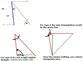
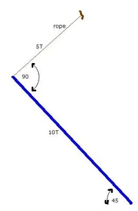
Just some thoughts on triangulating, they have to be right angled triangles.

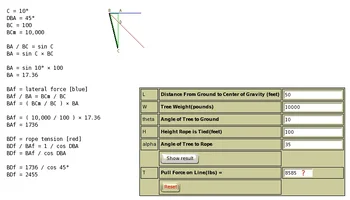
The weight of the beam is interesting too, same with a tree, because the weight is dispersed over the length of the structure, so it's not like we put a 10T weight on top of a 100 pole, the bottom 10' of the beam weighs 1T etc, the beam weighs 1T per 10'.

If you have trouble visualising this concept or understanding it then think about it like this.

You have a 6' long 60lb crow bar. You have the tip stuck in the ground like you do for prying rocks etc. The crow bar is uniform weight and diameter the entire length so not too hard to use. Now imagine if the crow bar had the full 60lbs at the top and the rest was hollow tube ... it would be harder to use right? Now imagine the crow bar had the 60lbs of weight at the bottom 1' ... much easier to use. Hence similar to a tree/beam, centre of gravity matters too, so I really dont think straight forward triangulation is the answer.
 

Attachments

  • 62850-vectorexample2.webp
    62850-vectorexample2.webp
    25.3 KB · Views: 52
Ok, sounds like some of this is whole tree & some is standing log. Are there two differant formulas?

EKKA, I got the 100' pole 1T = 10'

My question then is how do you formulate weight of limbs, branches,or leafs to get the "center of gravity" in your favor.
 
In my imagery; these forces wish to be linear; as the shortest, easiet path between 2 points. Also; either something is inline force to/thru a device or it is angled/not-inline. If it is not inline; it can be triangulated with right triangle. The inline force is minimal/the transferred force exactly/ without alteration of the force. So we take it and compute rest.

To do this, draw the inline; minimal/predictable force line thru the device; then the actual line of force. Then draw a perpendicular line off the nearest inline end (so angle between inline and actual will be less than 90) until this last line goes thru actual line of force to device. The perpendicular line off of inline, forces the triangulation to be a right triangle. Unless drawn line is pairallel to actual line of force; which means they can't intersect because actual force line is perpendicular to inline on device; but then that in itself forms a right triangle of bieng perpendicular to device/support etc.

The minimal/inline force is predictable/ raw unaltered force passed to it; lines that aren't are triangularily calculable by drawing this perpendicular line thru the predictable inline force position and comparing the actual line of force to this perpendicular line IMLHUO(In My Lowly Humble Unschooled Opinion!).

orrrrrrrrrr something like that
crazy.gif


And so i say again...(in signature)
 
[ QUOTE ]
gimme a break guys. I'm going elsewhere.

[/ QUOTE ]

Hahaha, have you heard of the saying ...

... if you cant blind them with science then baffle them with BS?
icon314.gif
This thread is getting a bit intense.

Yes, you have to consider the centre of gravity, I figure the easiest way of doing that using your skill in imagineering is looking at the tree and saying "where would I put a sky hook to pick the whole darned thing up and have it balanced?"

You know when you are rigging branches that you get good a guessing mid point ties ... neither butt or tip heavy. well, just try doing that with the tree.

We are talking about arriving at a formulae aren't we? So I think these things matter.
 
Here's another diagram. Here we say the 10T beam is on a 45 degree angle and the rope off the top is at 90 degrees to the beam.

Would you agree that the force on the rope is 5T in this instance?

63068-vectorexample3.JPG
 

Attachments

  • 63068-vectorexample3.webp
    63068-vectorexample3.webp
    6.4 KB · Views: 41
It would be 5T 90° to the load if the load were laying on the ground. Less in the air like that, I'd say. Something on the order of 4.14T?

I'm working on a little something in some free time. It should be ready before too long. Seems to me that the pull calculator linked to earlier from the forestry forum is not right and I'm trying to figure out how to correct it. I'll attach what I've got so far (remember, it's a work in progress).
 

Attachments

  • 63094-I_see_it.webp
    63094-I_see_it.webp
    22.7 KB · Views: 54
Erik, upon further reflection, I think the proper way to figure the weight on the rope perpendicular to the end of the object would be to consider it a tangent along an arc encompassing a quarter circle. At the vertical position the tension would be zero and at the horizontal position the tension would be half the weight. At mid-arc the tension would be half of the full possible weight, or one quarter. One quarter of 10T = 2.5T.

Here's a text file (save it to disk and remove the .txt extension; then open it in your browser and try it) attached.

The equation is:
T = (W * sin theta) / cos (90 - theta - alpha)
 

Attachments


New threads New posts

Back
Top Bottom