reverse MA

Kathy\'s Question

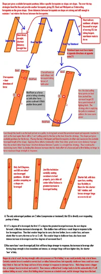
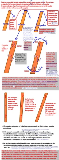
i was werking with some pulleys and the Dynamometer with some 10yr. old mens today (they help make me feel tall!). i was coming up with some simpler explanations, i think.

We had these pulley systems nested to compound/multiply their powers. They were pulling a hefty 1500#, each taking turns, few pix... There was a single line pulling on the dynamo registering 1500# when each took turn pulling, so we calculated it must be holding 1500# per line pretty quickly. A change in that came at a dropeye/becket pulley at the end of the single line; so we figured that was 1500/3 or 500# per line (3/1, easy to see, fer them as 1500# line was fedding into 3 lines most definitevely)after awhile. That fed into a 5/1 system, so 500#/5 per line etc. The lead 3:1, to move a load 1', you'd have to take 1' out of each of the 3 pull lines; or 3'input effort pull, to get 1'output work at 3x power. So, we are just funnelling 3' of work into 1'.

Also, If you had 300# sitting in a 3 square inch tiles; that would be likewise (as pulley systems) 100# per square inch. If we concentrated that into just 1 of the square inch tiles, that would be 300#per square inch(tile). In each case, no gain, no loss, just rearraingemeant; so that A always equals B. It is just factored different on each side; Like 300# lifted 1' (or into 1 square inch in tile example); is equal force/ work effort input, as to lift 100# 3'(0r 300 sitting on 3 square inch tiles etc.); which is equal to 20# lifted 15'. They all equal 300 foot pounds of work effort. Foot pounds right away telling you distance X power.

When, you turn a wrench, the longer it is the more easier power turning nut. The big circle of your turn of hand, is picking on, focusing/funneling into the little itty-bitty small nut, that in turn, takes advantage over the threads/real work. Just more distance, funneld into a smaller distance, so more power. Just like if 300# sits on 3 square inch tiles, or 1, determines how much pressure per square inch. We talked about how in some theif movies, they keep from setting off the pressure alarm in floor with some type of ski etc. spreading weight out to that of a dog etc.

If all the distance for turning the nut, was walked straight out, instead of in a circle, it could be several feet, taking you away from work. Like the recycle symbol, the circle allows us to stay in 1 location, turn nut 10x, and not be going back and forth or finish 20' away. The pedal crank on a bike, is a larger circle than the chain sprocket it drives, therefore concentrating /funneling power into smaller space/less tiles. So we have power increase. If sprocket arc was larger than pedal arc, that would be diluting, spreading your force over a bigger area, losing power faster. So, the smaller crank in front gives more concenttration of your power, while the larger sprocket covers more distance/speed but with less power for starting off, going up hill. But, each crank is driven by the same pedal push, so all equal/no magic, just L-earn your math!

Water pressure the same way, squeeze a forced pressure through a smaller hole, it has more power, everything equaling out keeps every act/force in balance. Every act and force bieg in balance, having an equal and opposite, means that the whole world stays in balance! Any changes in power speed/distance are jsut rearringements, not magic divine force. A car engine has a certain power output, transmission is leveraging circle gear system, that gives more power or speed etc. So, we talked about 2 speeding a screwdriver by turning either the handle or the shaft, to pwer the same screw. The shaft gives speed, the handle power in our little transmission. Then it was swim time.


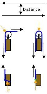
Glens- the Flash animations are vector, not raster graphics; and can be strategized to lots of animation etc. in a very small filesize by use of symbols reperesenting repeated graphics, isntead of the graphics themselves each time. Such as in this BarberChair animation @ 55k. Which also illustrates at full screen size that the vector graphic can be enlarged many times with no loss to definition, or increase in filesize, like regular raster graphics. All your comments about filesize etc. are partially what kept me poking around till i came up with this.
 
Hi Ken,

I think I now understand what it is you are trying to do, but as far as the hinge is concerned there is really only one external force (the pull from the rope or lift from the wedges) and the internal pull created from the weight of the tree. And as you have stated the weight of the tree only becomes significant as it (the CG) moves farther in the vertical plane from the hinge. To me the only way to get more pull is to increase the pull on the line. Put a 2:1 or 3:1 on the pull line if you want more pull, but you are not going to get anything significant from lacing down the back. I look forward to seeing your flash animation when it is done. Which tool(s) are you using to create it?

Cary
 
i was referring to doing it in Flash. In respect to y'all mebbe call it 'Shadowy Physics'. For one of the lead premises is that the shape is just available positions/points for forces to work with/against each other on. So the shape that we see is less important/shadowy, it is the force points on the shape, their direction and relation to each other that decide things. Shapes don't move or bind things, forces do. The same relationshoip of forcepoint diretions/positions in a beam, your arm, a tree, a blade of grass etc. gives the same results; given that the strength and stiffness the shape beteween thes postions is relative to/ will carry the forces without breaking or bending to releive them. Lineing up CG with support gives balance, wherever that CG is in shape. Only such lined up/inline forces are unleveraged.

A 2/1 or 3/1 give more power, but is linear Zer0 degree (U-shape line) bend, is inline like 180(straight-no bend). The force inour zrig etc. is leveraged comparing input to output as expression. But not leveraged in the not inline/ angular, rotating target instead of just pulling target sense.

The promised equal and opposite reaction; is opposite in direction, therefore the 2 lines complete an axis from the intiation point or bigger line. So, this is linear; the only way to capture to use the equal and opposite reaction to get more power is to arc the linear element headed the wrong way and make it react on the targeted load again. Our zrig etc. arcs/bends to the only other inline position Zer0.

When we do that folding it back on the system itself, it seems to confuse the eye, as we are watching the patterns of the shapes, and not the forces, i think the eye becomes confused. Like in DdRT, Spanish Burton, that 13x in ship rig, rotational force in dutching just lean side of face, pulley on anchor to feed opposite hand's equal and opoostie pull into target load too.

i think bending/arching line on load like this, gives 2 pulls on load, that are properly placed at farthest reaches from CG as to levrage with each pull, then their directional combination of compressing but not inline gives the tourque kinda event to bump CG a hair forward, more powerfully. Thus faking out hinge as to how heavy/leveraged a tree is on it, and forcing a stronger hinge in response. i think anything with this pattern of forces, must react likewise. i think just going 1' over top and tying off is improper, that sets Hitch as mid point between CG and Bend forcepoints. We want the CG to be in center of Hitch and Bend forcepoints.

Follow the initiation and path of forces, and how their relationships on a shape, not the shape. Am not home/am on ark duty(2cats, 2 dogs, hermit crabs, fish, giant lizard, 2 dragons and some specialty kinda other reptile; complete with screeching parrot), so haven't been able to do much but stew on how to express in Flash, which can be the longest yard of that anyway.

i maid this though in Paint, and got it down to 91k following some of Glen's hints. Could do much smaller, with more stuff and have motion too, all at oncet; in Flash
 

Attachments

  • 28057-ShadowShapes.webp
    28057-ShadowShapes.webp
    260.2 KB · Views: 59
Ken,

You are not rotating the stem about some midpoint by pulling on it from the top, which is what you're doing whether or not you're lacing the line back down the stem. Your "arcing" the line has no net effect here.

If you actually were pivoting the stem about the midpoint and that midpoint was not in line with the laced portion of your rope, it would add or subtract some (minute amount of) torque about that midpoint depending on whether the pivot (midpoint) was your side of the laced leg or on the other side of it, and proportionally to the offset between the pivot point and the laced leg, and with zero friction at the lace point. Since your "device" has the pivot point outside the confines of the laced leg, that leg has no effect upon the pivot.

If you were hinging a curved stem at a point equidistant from the two endpoints of your laced leg you might be able to achieve some effect like you're espousing.

Glen
 
Ken,

You are correct flash is a program from macromedia, but it is also the name of the file format. There are many programs that can be used to create flash files and by your context you are/were referring to the flash file since that is what one would download. FYI there are a few free programs to create flash files, but I'm sure you got a deal on the macromedia program.

As far as a confused eye goes, I don't think so! I solved the 13x rope rigging problem in a few seconds. You are correct that the trick is to focus on the forces and their relationship to each other. Looking at your diagram I can tell you exactly where your confusion is. It is that the force created by the back lacing is tangential or some significant angle to the log. It is actually parallel to the log and hence creates very little torque.

If this doesn't help clear things up let me know and I will create a detailed diagram of the forces and their relationship with each other.

Cary
 
Fascinating discussion.

When composing, use complete sentences. A complete sentence has a subject, a verb, and an object. Example: He hit the ball.

Try this: Every place you put a comma, instead, use a period. Every place you put a period, use a new paragraph.

Another hint: Use the first sentence to summarize your entire post. That way, we will know what it is we are about to read.

Of course, this is only if you are interested in people understanding what it is you want to say.

Thanks.
 
Even though you replied to my post I assume you are mostly referring to Ken's posts. I try to do a reasonable job with my composition, but often because of time constraints material get posted that is not book quality.

Cary
 
Cary,

I'm sure that was merely a consequence of using the "Quick Reply" form box.

Ken,

Here's an attached annotated version of your most recent image. Have fun!

Glen
 

Attachments

  • 28108-AnnotatedShadowShapes.webp
    28108-AnnotatedShadowShapes.webp
    303.3 KB · Views: 53
Well, i guess i'm guilty of writing as i speak, not focussing on punctuation all ways....

Dr. Glens; w'ar to start! The word on neccistate on hinge i think is equitable, not same as forced response? If shallower lean has less leverage on hinge, then lean neccesitate's less strength in hinge in response. In a steeper lean, more leveraged load on hinge, as soon as we plink 1 too many threads/fibers with saw, hinge folds. So, folds ealrier with more load.

Maximum leverage will be at 90deg./3 o'clock. No leverage, just load at Zer0 degrees, 12 o,clock. Halfway point is 45deg.; 1:30. But, half of levrage potential (that occurs at 3 o'clock) is achieved at 30degrees/1o'clock. If you open the Leverage of Lean Spreadsheet/Calculator(Excel)i have added the ability for reader to adjust degrees, loads and lengths, push Enter abnd it crunches it all for you. Playing will show for every degree more of lean, an increase happens in loading, but most intense in 1st few degrees right off 12; only marginal increases in loading per degree near 3o'clock. So, any tree falling between 12-3 experiences increasing leverage on hinge. Shallower leans near 12, get a higher increase in loading per degree of movment. So, they would stress the weaker hinge they initially neccesitated more.

This can help in climbing/rigging of horizontals then, for we are at maximum necessitated hinge strength, but moving towards less leveraged loading going from 3o'clock to 6o'clock. In fact even branches near horizontal/3o'clock, will force/necessitate a stronger hinge as a passive, matching system to force on it. The changes of loading in this range are marginal, so can say 2:30-3:30 forces strongest hinge, then decreases in leverage against that hinge as movement/fall continues.

In general, like using a pulley to bend line, i see 2 pulls on the work here by the line, not 1. i think non-inline forces competing on shape gives turn/tourque. i think inline is minimal loading that system will assume if it can. The out of line forces, creating more tension leverage, that system will try to use to adjust/turn towards minimal loading. The position of minimal loading/path of least resistance; calls the load to that position, and ease it's loading.

Here are some of the theories applied to the pulley systems(72k). First 3 speeds/powers for a 5:1 compression jig for pretightening lines into nose of pulley as example. Then, carrying that into compound systems. More pulling points on a load, alters things; and their are different leveraged strategies for using the pulls i think.
 

Attachments

  • 28147-Morefocusontarget.GIF
    28147-Morefocusontarget.GIF
    73.6 KB · Views: 50
Ken,

You where so close on that one! You have some errors in the last pane when you added the LH and RH pulls. I also want to add that your usage of nonlinear in this discussion is incorrect. This is a linear system whether you are using a straight pull or a rotating torque. If this was a nonlinear system you would not be able to use superposition. I will also add for clarity that we are talking about the force going to the friction hitch and that we are ignoring all sources of internal friction.

So here is a description of the error. Using a 1x pull at the input (RH) we get 3*5 + 2*3 = 21x as you have already shown, but for the internal pull (LH) we get 1*5 + 2*3 = 11x for a total of 32x not 29x. Of course if you want maximum pull you grab the rope with both hands and pull at the input for 2*(3*5 + 2*3) = 42x.

Later today I will try to post the detailed picture I talked about earlier. I have some logs that I need to go load so they can make their merry trip to the mill tomorrow.

Cary
 
Yes, ya got me on the 32x, fergot to count turn on 1 end, thanx. i don't see pulling with both your hands on the 'normal input' alone as delivering 2x what 1 hand gives. Especially in a vertical posiition, where without the 2ndhand being at opposite pull, can't get pull greater than bodyweight with 1 or 2 hands. But, if all of body wieght hanging on right arm, then will add Lhand pulls compressing towards R as a hand pull, and increaseing the R.handpull to bodyweight plus L.hand pull.

On more of a horizontal rig, i don't think that pulling with both hands on main input gives 2x pulling with 1 hand. But rather can pull on an anchor with freehand and increase pull on input. But then, could take that hand pulling to anchor, and with same energy, pull at another point in system as i suggest, to get more power, for same work effort.

i think of these compression systems as linear/Zer0, straigth line/180 as only other linear/inline position. So, any of the leans, many of the rope pulls are non-inline/leveraged angles in consideration to the CG and hinge forcepoints, as well as each other.

Thanks fer catching the math there on power system, this is the range you can start snapping and bending stuff in an instant by hitting one of these combinations. Especially if that is locked off udner tension, and line/lever is bent later! As i call these compressions of our jigs as inline, coming perpendicualr to line is most leveraged angle to me; ereally leveraging. At this point, the compression jig is then to just pretighten line, reinforce it(as you would a long wooden lever as not to bend under load etc.). Then, come in with the non-inline strategy of bending the tightened line from non inline/anlge; perpendiclaur the best, to really bend metal etc.!

i'll make noted change later, created at other location; Thanx.


Edit: Can i have a few of the free Flash type softwares addresses please; mostly for Lady Che. Thanks.
 
Ken,

I just put an equation into my calculator and plotted the amount of torque that would be developed at the hinge if the hinge were strong enough to withstand it at each discrete point from 0° to 90° (90 being horizontal). The screenshot is attached.

I arbitrarily used a Center of Mass at 40' equivalent to 2500#, though I'd guess the shape of the curve should generally be the same for any values.

I did this, Ken, because I cannot use your online tool, not being a Windows user ( BTW, you should check your pages at http://validator.w3.org ). Does it match what your tool produces for those values?

It confirms that the rate of increase of possible torque production does taper off as the angle progresses toward horizontal. The rate decrease does not appear to be very dramatic in the initial stages, however.

Glen
 

Attachments

  • 28212-plot_both_crop.webp
    28212-plot_both_crop.webp
    34.5 KB · Views: 51
i have come to understand that FrontPage makes not the best/neatest/shortest code, and am L-earning DreamWeaver to ammend all that.

Dramatic i guess is gonna be a lil'objective notation. Here is an old screenshot (83k) of spreadsheet. This is example has different numbers loaded that the online spreadsheet, but as Glen denotes, will run the same patterns at the same angles.

i think in general the patterns show, that a shallower lean will have the furtehst to travel, but also force the weakest hinge to do that job, and have more increase airtihmetically or geometrically in loading than a steeper lean would incurr, and more immediately.

Being based on the same alphabet soup as leveraging a line; i viuslaize the curves of the same basis.

i think the hinge will match strength with the total leveraged pulls (and wedge pushes)to gunned focal as long as it can. There will be the promised equlan and opposite reaction, total balance of pulls. When the pull of the hinge is out of balance/less than the felling pulls/pushes; then the hinge folds; and almost matching strength is set at that force in hinge. So, we try to fake out the hinge response; make it respond with more strength; theorizing by these numbers shallower leans need this more than steep. for a steeper lean, sets it's inital hinge strength at much closer to the total leverage potential load(horizontal), and has less distance to fall, requiring less face opennness and flexability of fiber to carry it this shorter distance/arc.
 

Attachments

  • 28248-LeverageofLeanIncreases.GIF
    28248-LeverageofLeanIncreases.GIF
    80.3 KB · Views: 46
[ QUOTE ]
That's my favorite calculator. The sx rules.

[/ QUOTE ]
Since this thread has wandered somewhat far afield of its original track...

The EQ was 'SIN(X)*200000=Y', with 0 90 XRNG, 0 200000 YRNG. The same exact plot is generated with 'SIN(X)=Y' and 0 1 YRNG (yeah, go figure, it's a sine curve).

Those screenshots are from "x48", the program source code of which I'd discovered in a comp.sys.hp48 posting coming up on 10 years ago. The post mentioned development on Linux which instigated my introduction to that. I've been Microsoft-free now for some-into my 9th year! Anyway, I'd dumped my 48S ROM via serial cable to my PC and that program runs the ROM image. HP has since made the ROM images for the 48S/SX and 48G/GX freely available. As I recall, the last iteration of x48 will run either type ROM and will do so with the appropriate "face".

I use an IBM Model M keyboard, so the "calculator" keys have a pretty good feel, though still not the same high quality of the exquisite keyswitches on the "flesh and blood" calculator! In x48 a mouse press on a key on the calculator will visually depress the key. BTW, to rub your nose in it, sarumono, I'd picked up an additional 48S with soft case (but no pocket guide) for $25 when HP end-of-lifed them! I'm set for life, I reckon.

Glen
 
Ken,

As luck would have it, you'd used the same 200,000 ft-lb (or is it really pound-feet we're talking about? I forget which is which, but there is a difference) achievable torque value in that attachment as I'd used in mine. The distance and weight values differ but that's immaterial. I plotted the graph again on my calculator and was not surprised in the least to find that at the 10° increments the values matched yours.

If you inspect the lower graph in my earlier attachment, even though it has extremely poor resolution, you'll note that the increase-rate of potential torque is actually rather gradual as compared to the impression one would get by merely noting the change in values as numerical figures in a chart. What I mean is, it's not exactly like suddenly falling off a cliff as opposed to, say, going down a steep incline.

Here's a question for you: if you grab a wrench 1' away from the "working" end which is on a nut, and you attempt to put 100# of force into the effort (100 ft-lb), is that much torque really being produced if the nut only requires 1/10 ft-lb to move because it hasn't come into contact yet with the surface it'll be clamping? Is the full 100 ft-lb not really being produced until such time as the resistance in the assembly can match that value?

What I'm getting at (and I may be all washed up since I'm un-formally-educated in the matter) is that the potential for a torque value being present in a system doesn't necessarily mean that value will be produced in a meaningful way at any given time.

With that in mind, your concept of "tricking" the hinge into behaving differently is something I find questionable. If the hinge will bend at a value much less than necessary to withstand the torque being applied to it, will it really "see" all of the potential?

If you flirt with the capacity of a felling hinge, aren't you in fact flirting with a barberchair? In order to "see" all the available torque potential, wouldn't the hinge have to be able to contain (not yield to) it?

Looking at it from the other angle, so long as the hinge will allow movement, does it really matter how much more than necessary potential is being presented to it?

Glen
 
Definitely on flirting with barberchair, and Stumper has outlined that you should only take the hinge so thick etc. for the lack of flexibilty proceeds geometrically, as hinge depth increases arithmetically.

On the wrench question, of course nothing is a singular act; everything a balance, so we can only match the present resistance. With a line pull or wedge push towards gunned target at FirstFolding we get thicker hinge. If tree is falling then, not needing to be forced more to keep from siezing. i think extra line pull weakens hinge/ adds load to cause to fall faster. Muscling/arm wrestling tree (by contrast)all the way down would be like FirstFolding was an extended event. So, pulls before FirstFolding kinda set up force to be available at FF(?). Pulls during FF can force stronger hinge. Pulls after FF can work against strategy, for maximum hinge strength is already set, now just forcing tree to fall faster/weaker. Looking to cut hinge slow, to use all the force in tree for slow/power, not fast/weak hinging (short of BarberChair).

i'm not advocating running it to full potential, just tweaking it, trying to keep hold of it longer and stronger, to have more control over direction and speed of fall. Sometimes cuz i need to, sometimes just for practice, and folding it all into rigging cuts upstairs. A lot of our tag lines double as a high leverage positon of pull on hinge, to flex it over stronger. Looking at using support line and hinge as supports during that critical/ easiest to impact time. TSee tree hinge as disposable support and cut free after rotation, or ground control drop sharply at that point to tear off. To get hinge strong, support man has to let tag line pull on hinge at FirstFolding.

i still kinda think, just because there is any increase (even if it was same increment per degree increase) in leveraging as tree tips, that for more healthy/stronger hinge it would be best to 'exercise' it. To force it to match a higher load than it's own at First Folding, to prepare it for it's journey of ever increasing leveraged load.

i think the numbers show, that would be of more importance from a shallower lean (if this was target strategy). By 'virtue' of more increase in loading and travel on the weakest forced hinge that a shallower lean promises.


A commonality in these topics/ sidenote. i have always seen this rotational down/up on opposing ends strategy (like in over the top and to bottom/mayhem lacing) in the Dutchman in lean side. Here again we warn of BarberChair, with any dutchman, but this isn't across full face, so doesn't remove releif of tree going forward to force barberchair. Instead this strategy offers the offside as relief, just closes the lean side. But, of the finite matching force of the hinge/face to leveraged tree/available force; i think this strategy applies those forces the best/rotational against sidelean (with tapered hinge). i also think that a tapered hinge is superiour against sidelean, for it's placemeant of more fibers in higher leveraged positions. The increased number of positions are better leveraged by distance and also angle of support to the sidelean i think. Being directly inline, and to rear of lean as a better angle of support, that also pulls across.

BarberChair and Step Dutchman Not home, so can't give ya the individual (smaller) Flash Pages (under 50k); just have this general one.

No formal education hear, nor is greek a second language. Just another watcher!
 
[ QUOTE ]
With a line pull or wedge push towards gunned target at FirstFolding we get thicker hinge. If tree is falling then, not needing to be forced more to keep from siezing. i think extra line pull weakens hinge/ adds load to cause to fall faster.

[/ QUOTE ]
That first sentence reads like your previous statements such as "[this situation] forces a stronger hinge".

If what you're saying is that outside assistance allows the use of a stronger hinge, then I agree. If not, I can't fathom what it is you're saying.

The second quoted sentence is something I completely agree with you about. Mis-management of additional force application could fail a hinge.

Anyway, Ken, the reason I'm jumping in right now is to tell you about http://www.inkscape.org/ where a new release was recently announced. It's a free program for dealing with Scalable Vector Graphic creation/manipulation. All discussion I've seen about it so far makes it sound quite capable and accessible to use. I'm fixin' to download the source in a moment on my way to bed, but there's a Windows executable already made and available at sourceforge.net.

Glen
 
Thanks for the link, i guess i must download all files seperatelY??

A 20 degree lean, just by virtue of it's more leveraged position(than 10 degree lean); therby load on hinge, can force a stronger hinge without barberchairing. Then, we should be able to force a stronger hinge at 10degree lean with line pull without barberchair threat.

We do this with branches all the time especially. A throwline over the end even gives good pressure for this. Wrap weighted end around anchor, have quick 2/1 pull with throwline on leveraged end of branch to force stronger hinge.

When rigging and have real tight line on load, might let some line slip right at frist folding to force strogner hinge, then 're-catch' limb with line, then proceed with stronger/meatier hinge and tight line as 2 spread aprt supports on load.

The direction of this pull is very important. In good wood, i don't pull agianst the sidelean, i pull to gunned center/focal of face, and let strogner hinge X leveraging of hinge fight sidelean. Pulling directly or partially against sidelean, unloads hinge by that much, as you address sidelean directly. It is the loading that gets the equal and opposite force to give support, jsut as it forces the hinge.

When rigging across with tight line; i cut down first, to load the line more, to get mroe pull from it. If i just cut across to target, i carry on hinge and not line, and as line moves clsoer to support without pulling down, it actually grows more slack. so, once again i 'fake' it out. i cut down, when intending to go across, to laod the line purposefully, then acorss to use that built up tension/power. Similarily with out line will cut one way to tension fibers forward towards face, then adjust saw angle to steer, with those more tensioned fibers. Direction of the added force is very important i think.
 
Ken,

Here is the material I said I would post. Things have been very busy around here the last couple of weeks so it took much longer to post than I thought it would.

But first some comments on the recent posts. I think using a pull line or a trees lean to increase the hinge thickness is OK to a point, but like Glen mentioned you have to make sure you don't go too far and barber chair the tree. You are getting a bit of protection by your back lacing being tied just above the notch, but the forces involved can easily be more than your average pull line can handle. So please be careful!

See the attached file for the diagrams.

First off, the CG is really only important for determining how the logs weight will effect the system. The pull lines in the various configurations we have talked about can be analyzed separate from its effect since this is a linear system and superposition applies. Also I can back any of this up with a bunch of math, but I would prefer to keep this at the intuitive level. So with that behind us here's a simplified back lacing analysis.

As you likely remember from earlier posts a moment is created by two parallel forces that have opposite magnitudes that are separated by a tangential distance (see the top of the diagram). So the trick to calculating the moment created by the back lacing is to determine the distance between the forces.

The center pair of diagrams show the top connection using two limit conditions. The orange arrow represents the effective force point for each case. For the normal pull line application (2x the height) the effective force point will be closer to the left point than the right one. A rough number is probably half way between the center of the tree and the bark.

The bottom pair of diagram show two possible lower connection schemes. The left one is probably what you are using. A loop of rope around the tree. The exact effective force point is dependent on the individual tree, but the fact that the rope has some slope to it implies that the point is not at the surface. I will be generous and say the point is about a quarter the way from the bark to the center of the tree. The right connection which uses some sort of hard connection eye bolt, etc. has an effective force location very close to the bark.

So now we have an idea about where the two forces are located. To calculate the moment we have to determine the force and the appropriate distance to use. In an idea system the force is equal to the pull line tension. In a real system it will be reduced by the frictional losses at the top connection. Lets use 120 lbs for the magnitude of the force. The direction of the force created by the back lacing is constrained by the top and bottom attachment points to be parallel to the center of the tree (vertical) and we have already guessed that the two points are about a quarter the radius apart. So we have about 30 ft-lbs/ft of tree radius (15 ft-lbs/ft of diameter). Which is insignificant compared to the force created by the CG or the moment created by the front part of the pull line. The vertical distance between the two points can be a few feet or a few hundred feet without any change in the moment created by the back lacing! It is only the perpendicular distance between the two forces that is important.

Cary
 

Attachments

  • 28685-tree-pull.webp
    28685-tree-pull.webp
    4.2 KB · Views: 60

New threads New posts

Back
Top Bottom