RADS Theoretical Ratio

As shown, both of the lower configurations are 3:1 systems. In reality the the lower left would be slightly more efficient because it uses one less pulley.

OTOH, no one would connect a stretcher like any of the three diagrams - they're not stable.
 
[ QUOTE ]
...I never said hybrid DDrt or DRT (still dont know what the differece is), but a hybrid 2:1 when refering to the traditional double rope climbing set-up....because of the difference between a climbing 2:1 lets say or a traditional hauling system. I feel the need to call it something out in the field working with young climbers, but without being too long winded about it.

[/ QUOTE ]

Reg, the acronyms DdRT and DRT are used to distinguish between two systems. DdRT stands for "doubled" rope and is descriptive of our traditional climbing system, when one rope goes around a limb and is attached back to the climber; e.g., "doubled" but one rope is used.
A second, small "d" was added to the acronym DRT (double rope technique - meaning use of two ropes) to make it clear that we were using a doubled rope and not two separate ropes, as is common in other fields of rope access.
This is why, I personally feel there is no need to invent new terms to separate tree / ground systems. We have the terminology already in place with these acronyms, as DdRT, DRT, SRT and RADS that describe climbing specific systems.
They can be described and used in context without fear of confusion because we would never use those same acronyms to identify a ground-based haul system, right?

Dave
 
[ QUOTE ]
However, if this were a parallel rope system as shown in the figure below, it would be a 3:1.

[/ QUOTE ]

Nice diagrams, Ron! I think the last one is the one Reg is talking about. Why do you describe it as 3:1?

It seems to me that if you pull down on the rope the plank will simply rotate around its center of mass doing no work and requiring no force. After rotating it a few degrees, Reg steps on the rope and lifts on the cam end of the plank. Now, yes, work gets done and force is required. The lifting step is just a lever with a 2:1 MA. The whole assembly is sort of a weird unidirectional teeter-totter in which the fulcrum is replaced with ropes and pulleys. It is not really a pulley problem at all.
 
[ QUOTE ]
[ QUOTE ]
However, if this were a parallel rope system as shown in the figure below, it would be a 3:1.

[/ QUOTE ]

Nice diagrams, Ron! I think the last one is the one Reg is talking about. Why do you describe it as 3:1?

It seems to me that if you pull down on the rope the plank will simply rotate around its center of mass doing no work and requiring no force. After rotating it a few degrees, Reg steps on the rope and lifts on the cam end of the plank. Now, yes, work gets done and force is required. The lifting step is just a lever with a 2:1 MA. The whole assembly is sort of a weird unidirectional teeter-totter in which the fulcrum is replaced with ropes and pulleys. It is not really a pulley problem at all.

[/ QUOTE ]

Your comments assume we would allow the stretcher to rotate.

If we take the upper diagram as an example, and the stetcher starts to rotate, someone could maintain balance with an additional counter force. The system would be 3:1.

The hauler may have to pull more or less force than the theoretical 3:1 would imply depending on whether the balancing force is upward or downward, but while in balance, it would remain a 3:1 MA.

The same would be true for the lower left configuration. The lower right might be a bit more problematic to keep in balance.
 
[ QUOTE ]
The first one Ron, thanks. Ive used it to load logs in the past, but with no pulleys. Thanks Dave

[/ QUOTE ]
Ahhh, I thought the first one was what you described!

BTW, did it stay in balance? Of course without the pulleys it's a different situation. Friction would probably help with balance where pulleys might be more problematic.

Oh, just curious, is it about 3:45pm or so where you are? It's 10:45am here.
 
Reg,

Now that I know what set up you had in mind, here are some things to consider, although I'm not sure how significant they are because often in the field, we have to work with what we have. I've reproduced the configuration here for reference:

Keep in mind that this is not stable and will require some form of balancing, you or perhaps a helper.

Regsstretcherexample-1.jpg


There is one point of interest and one fairly critical issue.

First, the angle formed by the anchor pulley and the two ropes coming from it. This is NOT a parallel rope system so it can have a different theoretical MA than a parallel rope system. However, assuming stretcher connections 7 feet apart, if you keep the distance from the stretcher to the anchor pulley 20 feet or more, it will pretty closely approximate a parallel rope system.

Note that the sketch DOES NOT represent the 20 foot distance; it is much closer than 20 feet to emphasize the angle that can form.

As the distance decreases less than 20 feet,...

update/edit:
I did some number crunching with regard to this and it's a lot better than I had remembered. Even if the angle formed by the rope at the upper pulley is as much as 30°, the difference from a parallel rope is only about 10%.
end edit........

the angle formed by the rope can change the theoretical MA - just something to be aware of. But, if the sretcher tie-in points are 7 feet apart, as long as the distance from the stretcher to the pulley is about 15 feet or more, it's insignificant (no worse than 10%).

The second issue is the angle you pull the pull line at. If the pull line is near vertical and the above condition is met, it will give very close to a 3:1 MA. However, if you pull the pull line horizontally, the theoretical MA decreases significantly. I didn't crunch numbers on this but it makes a significant difference.

If you pull the pull line below horizontal, the theoretical MA will decrease even more.

Just some things to keep in mind more than anything else I suppose.
 
Verrrry good Ron. Almost tempted to start an 'Ask Ron' thread right here. Would be great for us, and you'd probably grow to enjoy it given time.

The load tilts until you raise the cam end, then you can straighten it up again single handed.

Its near 1:00 pm now....relative to this user I mean
 
[ QUOTE ]
Verrrry good Ron. Almost tempted to start an 'Ask Ron' thread right here. Would be great for us, and you'd probably grow to enjoy it given time.

[/ QUOTE ]
You may be giving me a more credit than I deserve. Probably would be fun, although I'm not sure I'd last long before I couldn't answer a question.

[ QUOTE ]
...The load tilts until you raise the cam end, then you can straighten it up again single handed.

[/ QUOTE ]
Hmmm, now that's just cool!!! See I would have missed that right there. I'm already down one and nobody's even asked a question yet.
frown.gif


Edit:
After thinking about the rope being over a limb instead of a pulley, and from the way you describe the tilt and corrective action, you may only be getting a 2:1 at the cam because the rope friction over limb may act more like a fixed point than a pulley. In any event, the friction over the limb would significantly reduce the effective MA.

[ QUOTE ]
...Its near 1:00 pm now....relative to this user I mean

[/ QUOTE ]
I got it at 5:01 - we're closer than I thought - hey wait a minute - you did that on purpose - that 'relative to this user' - that's what I've been saying, "relative to the climber."
grin.gif
 
The problem posed by Reg, shown by Ron as diagram #1, is very cool indeed.

Let's simpify the problem according to Ron's suggestion by removing the triangle effect. An easy way to do this is to shorten the plank down to a simple weight, as shown in the diagrams below.

3pulleys007Small.jpg


In drawing A we have the standard familiar 3:1 MA pulley setup. In all three diagrams we assume perfect pulleys, so the tension in the rope is everywhere the same. The analysis of this setup has already been beat to death several times over in this thread, so I won't repeat it here.

Drawing B, pulley-wise, looks like a 3:1 but it's not. There are two rope legs equally supporting the weight, so each of them has a tension equal to half the weight. The diagram as shown is impossible--there has to be some horizontal force exactly opposing the rope pull, that is, a force of 1/2W pushing the weight to the left. This could be Reg's assistant as described earlier in the thread.

Drawing C, pulley-wise, also looks like a 3:1. Reg's assistant is still having a morning coffee so there is no opposing force keeping the system plumb. Everything falls into equilibrium when the supporting lines are 30 degrees from vertical. The tension in the supporting rope has gone up from .5W to .577W. Since we are now pulling harder to lift the same weight, our mechanical advantage has gone down, as shown.
 
If by chance this has been overlooked, I'm pulling from inside the cam. Sorry Moray, Ron....but at least I'm keeping up the trend. You guys are the best btw
 
In the top figure of my original sketches, I tried to indicate that the pull line could vary, which obviously it can, and I alluded to that in some of my comments, but most of my comments were based on the understanding that the pull would be vertical - which I did not show in the original sketch. Other than that, all three in my original sketches are 3:1 - with the qualification mentioned above that the pull in the top is understood to be vertical as discussed rather than shown.

As Moray also addressed, as the pull angle changes from vertical, the MA will also change - moray's sketches help show how and why that happens.

Of course this is a drift from RADS theory since a RADS is a parallel rope system. But at least we can see that those nice integer ratios, i.e. 3:1, 2:1, etc. that come from parallel rope systems, can actually vary with the angles in the systems and that can produce fractional ratios.
 
[ QUOTE ]
TLHamel,

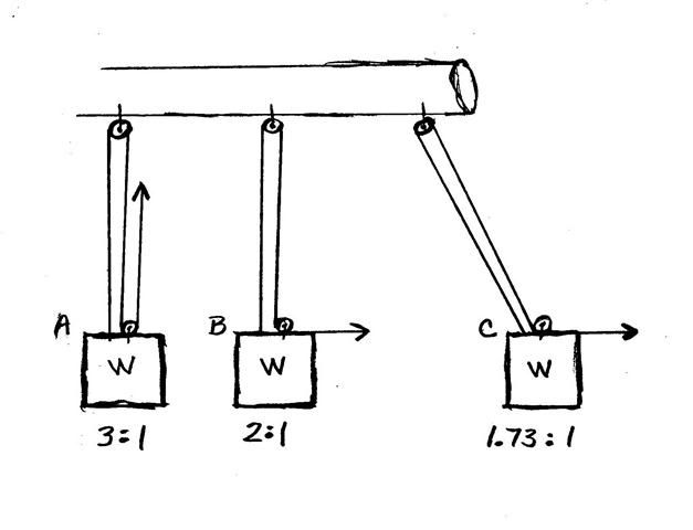
You are seeing a 2:1 because you are ground referenced. You don't move off the ground at all, so you are ground referenced. The system is not supporting your weight at all. If the system had you fully suspended, there would be three lines supporting your weight, not two. When you pull yourself up you would only have to supply a force equal to 1/3 your weight.

When you are suspended and your full weight is on the system, you will move up one-third of the distance of the line you pull.

What's so deceptive about this is that the climber is moving up at the same time his hand moves down. It is very difficult to see that the arm(s) actually pulls 1/3 of the force through 3 times the distance.

Here's an indicator. Get a scale and measure the force in the pull rope of an all pulley RADS (eliminating friction) and see how much tension is in the pull line. It will be 1/3 your weight, not one half.

I argued the very same thing, i.e. the RADS is 2:1, the same way, did all the measurements, etc., but then two guys, one a physicst kept insisting the RADS was a 3:1 to the climber and a 2:1 to a ground referenced person. I finally realized the "work" won't balance out for a suspended climber as a 2:1, but it does as a 3:1.

And throughout my arguments, in the back of my mind, it was forever nagging me that in a RADS, when I pull myself up, there are three lines supporting my weight. I could not resolve how three lines supporting the load could produce a 2:1 ratio. Well, it couldn't. So I had to really study a pulley system where the pull line attached to the load and produces an extra support line. I finally saw the light thanks to a buddy and a physicst.

Here's a discussion of the 2:1 which I did as a preface to the RADS. It explains the very same concepts but with a simpler system.

http://www.youtube.com/watch?v=76l9KZ6XcME

I have the RADS version up, but it doesn't clearly show the distances that support the 3:1 ratio so I'm redoing it so it becomes clear the RADS (frictionless) is truely a 3:1 to the climber.

[/ QUOTE ]

Ron,

Description number 1:
In RADS, (assuming zero friction and parallel lines, etc., etc.) a climber has a mass of 150# and is suspended in air as a separate person holds the input leg of line.

That is: 75# of input force (person holding the input leg with 75# of his or her own mass)... 150# of output force (climber suspended by the two legs of line at the harness)... 225# of reaction force (at upper assembly). Three legs of line, 75# each.

Do you agree with description number 1?

Description number 2:
In RADS, (assuming zero friction, parallel lines, etc., etc.) a climber has a mass of 150# and is suspended in air and holds the input leg of line by him- or herself.

That is: 50# of input force (climber holding input leg with 50# of his or her own mass)... 100# of output force (climber, minus the 50# required to make the input, suspended by the two legs of line at the harness)... 150# of reaction force (at upper assembly). Three legs of line, 50# each.

Do you agree with description number 2?
 
[ QUOTE ]
...Description number 1:
In RADS, (assuming zero friction and parallel lines, etc., etc.) a climber has a mass of 150# and is suspended in air as a separate person holds the input leg of line.

That is: 75# of input force (person holding the input leg with 75# of his or her own mass)... 150# of output force (climber suspended by the two legs of line at the harness)... 225# of reaction force (at upper assembly). Three legs of line, 75# each.

Do you agree with description number 1?

[/ QUOTE ]

Yes.

[ QUOTE ]
...Description number 2:
In RADS, (assuming zero friction, parallel lines, etc., etc.) a climber has a mass of 150# and is suspended in air and holds the input leg of line by him- or herself.

That is: 50# of input force (climber holding input leg with 50# of his or her own mass)... 100# of output force (climber, minus the 50# required to make the input, suspended by the two legs of line at the harness)... 150# of reaction force (at upper assembly). Three legs of line, 50# each.

Do you agree with description number 2?

[/ QUOTE ]
Yes.
 

New threads New posts

Back
Top Bottom