- Location
- georgetown ontario canada

Navigation
Install the app
How to install the app on iOS
Follow along with the video below to see how to install our site as a web app on your home screen.
Note: This feature may not be available in some browsers.
More options
You are using an out of date browser. It may not display this or other websites correctly.
You should upgrade or use an alternative browser.
You should upgrade or use an alternative browser.
How does MA work?
- Thread starter NickfromWI
- Start date
knudeNoggin
New member
Clearly TreeSpyder has his web straight when saying that one gains force on setting
up the shroud by anchoring the secondary tackle upon the very shroud--the tension
from the tackle is borne by that shroud (in addition to the principal tension got from
the main tackle. To the extent that this shroud stretches and the anchored tackle
moves, there is a lean towards 3-to-1ness of MA. (But I think that the Rolling
Hitch will roll out--the end isn't stoppered.)
*knudeNoggin*
TheTreeSpyder
Branched out member
- Location
- Florida>>> USA
i've L-earned a lot from ya, and with ya guys. But Dave i think that we can drop the 5/1 from the old ship's diagram(keeping mainline redirct pulley on anchor, just taking rest of 5/1), and keep the "2/1 or 3/1" part and anchor it outside the system by untying rolling hitch and using that tail. i believe then, it would be a 2/1 system in total(rig set in direction as shown as you said) Switch rig around we have 3/1; and can put bodyweight into it(if vertical rig). Hook that Rolling hitch back to position(so it sits as it originally did, pulling on load line from each end and not anchor) and i think we might be at 5x from what i seen, never measured.
i think this gives a compression system, that pulls on both ends of the rig instead of one, to compress more;and take rope purchase, than just pulling from one end; other on anchor. This has been what i've tried to express in rigging etc. for horizontal turns, 'mayhem' etc.
i think these same forces work inside knots, and these forces observed statically in rigs, are like knots and forces under a microscope. Power of leveraged length and leveraqed bend multipliers; main force and it's equal and opposite, strength and elasticity studies used by the rigging and knotting systems in the same way and science.
Attachments
- Location
- georgetown ontario canada
Dave and Ken,
I haven't scrutinized the entire "conversation" so far, but if you two are disagreeing on something here, I can say that the flashing diagram (why is it an animated GIF with only one frame?) Dave provided gets my stamp of approval for content accuracy.
It's a two-to-one system operating a two-to-one system, for a net advantage of four-to-one, with the top anchor point bearing an additional unit of one for the convenience of the (presumably human) operator.
Glen
TheTreeSpyder
Branched out member
- Location
- Florida>>> USA
Ummmmmmmmmm Dave i meant for the 2 red lines on top anchor to be seperate terminations; the same anchor is used 2x instead of drawing another one. so, though in your diagram, there is 50# total on that anchor; but 20# on 1 red line and 30# on the other red line.
Not to change the rules, but i am trying to effect loading on the yellow device thingy on top anchor at end of the L.Red Line. i beleive the scenario was to load that line/position as being more or less to support sail etc. i think the puzzle was to choose if the 3x/becket pulley end of smaller/secondary rig is connected to any anchor (not specifically one shown used with both lines for convenience)or to place those same pull(s) on the Loadline/yellow device as target position for maximum or neutral effect.
Quite humbley with a 10# input you place 50# on the anchor,and 20# on target(previous to anchor). If we take the 3x/drop eye/becket pulley off the anchor and friction hitch it below yellow as to mimic ship pic, we then get the full 50# on the target, that then remains the same 50# on the anchor also; i think. i try to do same in some of the rigging i've de-scribed.
Kenny,
I love you, man, but it's hard sometimes to get the gist of what you're saying.
Does the annotated attachment properly sum it up?
Glen
(edit: Ken, if you were the one that downloaded the image before I corrected and replaced it, fetch it anew)
I love you, man, but it's hard sometimes to get the gist of what you're saying.
Does the annotated attachment properly sum it up?
Glen
(edit: Ken, if you were the one that downloaded the image before I corrected and replaced it, fetch it anew)
Attachments
TheTreeSpyder
Branched out member
- Location
- Florida>>> USA
Greetings Glen;
Who'd think you'd join a conversation like this!!!?
Ummmmm i'm not trying to move the anchors; but get highest reading on the yellow 'scale'; where a sail etc. might be tensioned from in original ship rig neat pencil drawing(which KnudeKnoggin is VERY adept at!). So, the noted 4 or 5x pull in your drawing i would say is just for support/anchor load info, and not for the target work calculation. For this purpose(raising force on 'scale'), brining the 3x end of the pulley to pull on the load line rather than the anchor is best.
That way the 2-3 system pulls on target load with both ends, not just 1. The equal and opposite doesn't exit the system, but is recycled/folded back to system to pull on target load. It pulls the same on anchor or rope; the force is blind to these things we see, and is jsut running a loaded force pattern. Irrespective of the device it is put to; as long as that device can conduct the forces thru and their direction as any other.
You can pull on 1 corner of a grocery cart and resist equally with bodyweight/through foot ground contact; or you can pull 1 corner and place opposite and equal of that force to push the opposite corner, turn a boat same. Like a martial arts move, of pull 50# on wrist, with bodyweight as equal and opposite, or pull on wrist with 50# and push foreaqrm opposite direction with equal and opposite 50#. Putting more force to target, and the farther the 2 points are apart, the more leveraged the rotational force. Whereby the first pull is assumed as the other individual pulls as linear.
All the same pattern to me, close the system more to put more of the responding forces to target, rather than outside system so much. A version of mayhem to me. i think that works in every choke, running bowline, half hitch etc. all around us; just trying to identify to tap into it more often at will.
Orrrrrrrrrr something like that...
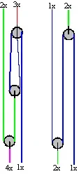
Okay, inspect this version of the image. It looks like we derive the same values on the lower pair but I'm not quite sure where you're going with the upper pair.
I just reviewed and added some comment to the image I was about to attach.
On both of the right-side configurations, as the red leg is pulling on the object, the long green leg would become slack if the "bottom" sheave weren't a sheave. Since it is a sheave, the slack is tended by the right-hand green leg.
I get the odd impression that the load on the "lower" spar would be somewhat less than four (upper diagram) or 2 (lower diagram) since the task of taking up slack would seem to subtract from the amount of effort working the load via the blue line.
Taking that approach it would seem that both right-hand-side systems would be nothing more than a way to have to pull more rope to do the same amount of work.
But the fact that more rope is being pulled to do the work would imply a mechanical advantage...
I'm confused.
Is this like trying to pull yourself off the ground with your hands while standing on them? hahaha!
What is the (plain English, if you can) answer to this puzzle? (and don't we both have better things to do?")
Glen
I just reviewed and added some comment to the image I was about to attach.
On both of the right-side configurations, as the red leg is pulling on the object, the long green leg would become slack if the "bottom" sheave weren't a sheave. Since it is a sheave, the slack is tended by the right-hand green leg.
I get the odd impression that the load on the "lower" spar would be somewhat less than four (upper diagram) or 2 (lower diagram) since the task of taking up slack would seem to subtract from the amount of effort working the load via the blue line.
Taking that approach it would seem that both right-hand-side systems would be nothing more than a way to have to pull more rope to do the same amount of work.
But the fact that more rope is being pulled to do the work would imply a mechanical advantage...
I'm confused.
Is this like trying to pull yourself off the ground with your hands while standing on them? hahaha!
What is the (plain English, if you can) answer to this puzzle? (and don't we both have better things to do?
Glen
Attachments
- Location
- NW Oregon Coast Range
Here is my simplified diagram. You can connect the top two or for that matter the bottom two connection points however you want and it will not change the forces one bit. The different magnitude forces are color coded and labeled at the edges. It should also be noted that the total force on the top and bottom must be equal. I am assuming no friction in the sheaves. Ken, I didn't understand your comment next to the lower sheave.
I hope this clears things up,
Cary
I hope this clears things up,
Cary
Attachments
TheTreeSpyder
Branched out member
- Location
- Florida>>> USA
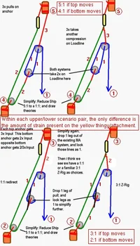
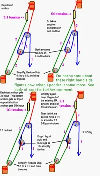
My diagram is supposed to be simplified version of the ship diagram of the 3:2 system piggybacked on the 6:5 system. In the ship system, the 6:5 served 5x effort to target, so i dropped that to 1x to simplify examination. i kept an odd multiple to maintain the direction of serving to the 2x of the 3:2 without any other alteration to the system. Now i think we were looking at if the 3:2 system; should place the 3x end to pull on the target loadline at the rolling hitch or exit the system to place the forces of it's pull on an anchor instead to achieve maximum force fropm same effort onto the target. i think some said they were equivalent values; the 3x could be alternately placed on any anchor vs. a more closed system of pulling on the target with more focus of the input effort and it's equal and opposite force to targeted work.
Cary; i think the notation you refer to, is about simplifying the 5x to 1x on lower part of system for examination of the ship system, to find if it quietly gives a tip for more power than hitching 3x end of 3:2 to anchor or hitch. i agree with the values in the system of your diagram, but not sure how that addresses where the 3x end of 3:2 pulley etc. rig gets anchored to, the moving positon on the rope inside the system, or the static position outside the system on an external anchor.
i think that the ship picture has the 2x of the 3:2 pulling on a 5x of the 6:5 to give 10x at 1 level of exameyenation. But, because the 3x end is purposefully pulling on the load line instead of external anchor with the force of it's pulls; i think the system yields 13x, not 10x.
If the 3:2 system was reversed, i think it would create 17x. But you would have to lift with legs to tension. In the mode shown, you could jump on the line to impact, push from underneath with legs and bodyweight, have several men pull, sweat in easier fo final line purchase too i think. So depending on the direction of the 3:2 pulling on the 5X, and if the other end is placing pulls internally or externally; we can create various pulls i think: 10x,15x with a pull exiting system from 3:2 or 13x, 17x if the pull in question is maintainted internally to work on the load i believe.
i think placing extra loaded points in the right direction on the work can make more power, even in soft devices using this force; one place to look for extra force is in closing more of the equal and opposite reaction etc. to focus on the internal work with their forces, rather than exiting the system with those gifts. This creates a more efficient system; sometimes leading to less support loads.
i think DdRT is just a simple example of this pattern of more focused effort and it's equal and opposite to the work; with as little force exiting the system as possible. i think a choke, running bowline, half hitch etc.; take what could be a 2/1 if pulling on external anchor, and bring the external pull to internal; so 1x push 1 way and 2x pull back. They are lined up on each other, so compression results. The 1x reduces the opposing 2x to 1x only exiting the system; so no more load on system, but much more ferocious grip by the system forces lined more up on target, and lined up on each other for compression. Spreading these 2 forces apart on a line can pull at 2 diffrent ends of it. Do same to something stiff like wood, forces lined up on same axis we have compression grip again; spread apart the forces we have a torquing spin/arc direction like karate/judo example, sharp turn of grocery cart, rowboat, more power to turn a valve, mayhem, self torquing rig etc. i think.
i don't think the forces know what they are connected to, so pull anyway; only our eye is confused by such things. i don't think that 1 end of the 3:2 system can pull without the other end pulling. We have a choice where to place that pull; internally or externally to the system. We can lift truck bed with a comealong through a pulley that hitces to truckbed, come along on an external anchor. Or we can DdRT comealong, take it off the external anchor and hook it to to the truck bed with the hitch; so it lifts 2x. The ship example just takes it a step further.
Edit: i keep forgetting to note that all the support pulls (except the 1/2xLoad one) on the previously listed sheet of Proper Ship Names of Power Rigs; their powers and support loading ratios; have not a round rope at that high load position, but a more splayed out/ flattened binding it seems for less leveraging around the turn on spar from the multiplied force of the purchases and tackles. Comparable to our use of flat rope/webbing, for same non levraging charachteristic on mounts.
Attachments
Ken,
Your nomenclature is confusing. Your use of "3:2", for instance, is wrong, I believe. You're using ratios (which are actually fractions) to describe the component count or something. 3:2 reduces to 1.5:1 and 6:5 reduces to 1.2:1 and I'm quite sure that's not what you want to be saying.
Perhaps this is a large part of the reason for misunderstanding of what you're saying?
Glen
TheTreeSpyder
Branched out member
- Location
- Florida>>> USA
By 3:2 i'm noting that the system pulls 3x on one end, and 2x on the other; i think the forces are blind to what they pull on, and just do their thing. So the same 3x can sometimes add to pulls on load or just pull against a rock; the forces don't care, they pull the same.
6:5 similarily denotes that the system takes that module's input and outputs 6x input on 1 end and 5x input effort on the other. So, the anchor on the lower rig module takes 6x input effort force, while the load takes 5x that module's input effort. This type expression also shows how that might be turned around, to place 6x on load instead.
On the top 3:2 module; we have a 3x input effort output position and a 2x effort output position. The ship drawing has taken/chosen the 2x input effort of that rig and placed it through the 6:5 system multiplier. So on that anchor is taking 12x input effort and load is taking 10x input effort.
That leaves where to add the 3x input effort position of the 3:2. Should we add that to an anchor outside of system? Or should we add it to the pull on the load?
Sorry for my uneducated nomenclature; but for the imagery/model i'm trying to convey; these system expressions seem best to me. i understand the ratios of the outputs you pro-pose, to me they are the powers of pull on input and on load only; but then they only show 2 dimensions of the rigs(1 as input and leg of output on load)and assumes the 3rd is useless. i try to show 3 dimensional in the same 2 numbers; assuming 3rd dimension is 1; and all 3 positions are loaded in ratio; and that the 3rd pull is usable; not just discarded as pulling on anchor; or irreversible. This 'nomenclature' describes whether 1 or 3 pulls are on the other end of a 2/1 system better too i think. De-scribed this way; the 13x rather than 10x pull on load is more recognizable too, i think.
Edited pic for more detail and changed arrow direction, per discussion with Glen below.
Attachments
As Cary made mention of, the "outputs" are really the same on both ends of the device. The "3:2" (using your terms) is really "(2 + input):2" because the input happens to be parallel to the system. If the input were from an angle 90° to the system and centered it could be perhaps something like "(2 + (5 × input)) 2 + (5 × input))" since both ends would be "seeing" the input force equally.
As I alluded to earlier, there would be so much "slack" being taken up with both systems used together on the load that it might become impractical for actual use without enough room in the system to accommodate everything needed to get the work done. And/or taking multiple bites in conjunction with a second system to hold purchased tension while the first hitch is worked back toward the load.
You make thinking fun.
Glen
2 + (5 × input))" since both ends would be "seeing" the input force equally.As I alluded to earlier, there would be so much "slack" being taken up with both systems used together on the load that it might become impractical for actual use without enough room in the system to accommodate everything needed to get the work done. And/or taking multiple bites in conjunction with a second system to hold purchased tension while the first hitch is worked back toward the load.
You make thinking fun.
Glen
TheTreeSpyder
Branched out member
- Location
- Florida>>> USA
i guess i should have more properly showed the input effort down; lines not angled apart. i was partially thinking electrical schematic of course were that doesn't matter so much. i've changed that arrow; and added some stuff to the last drawing above that we have been talking about. Of course how much pulling the input perpendicualr to the line system leverages the line would depend on the angle of the line at that input force. So, we would pretighten the system to to be as stiff/ reinforced as possible and lock off to ownself/floating. Then, pull perpendicular to tightened system to get highest leveraged gain. Anything pushed or pulled not with it's long axis column is leveraged, doing so perpendiularily from the stiff axis is most leveraged. The stiffer we make the system before perpediuclar pull, the more the system resists, the more the leveraged return/response.
i think we include the input pull as part of device output; to show integration force with other 'modules' of the system.
These things sure do pull a lot of slack; but the extra distance pulled, of course translates into more funneled distance force, into moving the load the same amount of distance. We will note that both ends of "3:2" are freely adjustable dynamic hitches, and not more 'static' fixed knot/bend positions, to facilitate the 3:2 to be adjusted to free up allthe pusrchase gained and dget another bite. We have the rolling hitch on the upper end, so to slide doesn't need disconnected. Then the most basic hitch, only on a hook to be called a Blackwall; but if pulled backwards is a crossed turn as the basis for Clove, Snuggle, Constrictor, Transom etc. family. The system can be seperated and carried to piggy back on other positions too; this is now i've used it in tiedowns for several points with only 2 pullies and redirectiong tie off through eyelet to this device, rather than just locking off to anchor eyelet. Especially on like a motorcycle, super tighten one side and compress shock, then go to other side.
Then bend the lines towards each other, binding together etc. after they are tightened stiff. Once again look at the rig that we usually use to tighten, as just stiffiening/ fortifying a massive lever before really leveraging tight. The tighter the great lever, the more leveraged force is returned at other end(s); with less 'leakage' lost at flex points. A gymnast's swing force can be conserved the same way, remaining totally tight and making the motion work for you and carry you with negligible loss in pendulumn or spin.
TheTreeSpyder
Branched out member
- Location
- Florida>>> USA
[ QUOTE ]
I know MA works, but I can't see how. Could y'all help me put it in layman's terms?
love
nick
[/ QUOTE ]
Dearest Nick,
i think there are 2 types of leveraging/MA with rope; both involve bending the line. Anytime you bend anything, you leverage it in an arc. There is an angular bend at near 180 flat of intense leverage over a short disstance. Then there is the commoner understood/ meant by MA linear strategy of producing power of using the other extreme angle of Zer0/bent around the pulley.
This MA, simply gives an increase in pulling points/legs of line; all theoretically equal to the initial pull. So, a 100# pull gets placed on a load with 5 pulls of 100# etc.. Because the pullies allow the pull of the line force to be folded back onto the load to take another pull etc. Straight lines carry power distances, but it is the bent lines give power. The most power gotten from bends are at each of the most extreme poits a bend can be: folded Zer0 degrees back on itself for pulley or near 180 flat.
Seeing as each of the 5 pulls, has to be shortened 10' each to move the load 10'; so 50' of rope is pulled, to get a load to move 10', with 5x power. We have taken 50' at 100# pull effort and funneled it into 10' of lift at 500# force. Really, no loss no gain; if we shoved more air into the same sized tank area, we would get higher pressure force. Here we are just shoving more power/distance into the same sized work distance, and getting more pressure/force.
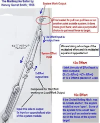
The shipboard rig gives 13x power (as extreme example) and not 10x, because the pulls are set on the load and not the external anchor with that odd 3x pull; so fits this rawest definition of increasing the pulls on the load to give more power. So, we can't always get all the rope distance pulled out to prove how much power, the system just has to be loaded with the positions of pull and trying to use them. Just as any leverage system should. It just takes it a step further and uses the promised equal and opposite force to do so, instead of even more pulleys to give more legs of pull. Take the ones off of the anchor.
The above can work over long distances. But in large, super prybar and massive wooden levers arched we only get small movement at very high power. Rope has a component of MA/Leverage like that too, when you arch/bend it; but only for short distances like large levers. And like large levers, the stiffer the line to be arched, the more of the leveraged power return.
I know MA works, but I can't see how. Could y'all help me put it in layman's terms?
love
nick
[/ QUOTE ]
Dearest Nick,
i think there are 2 types of leveraging/MA with rope; both involve bending the line. Anytime you bend anything, you leverage it in an arc. There is an angular bend at near 180 flat of intense leverage over a short disstance. Then there is the commoner understood/ meant by MA linear strategy of producing power of using the other extreme angle of Zer0/bent around the pulley.
This MA, simply gives an increase in pulling points/legs of line; all theoretically equal to the initial pull. So, a 100# pull gets placed on a load with 5 pulls of 100# etc.. Because the pullies allow the pull of the line force to be folded back onto the load to take another pull etc. Straight lines carry power distances, but it is the bent lines give power. The most power gotten from bends are at each of the most extreme poits a bend can be: folded Zer0 degrees back on itself for pulley or near 180 flat.
Seeing as each of the 5 pulls, has to be shortened 10' each to move the load 10'; so 50' of rope is pulled, to get a load to move 10', with 5x power. We have taken 50' at 100# pull effort and funneled it into 10' of lift at 500# force. Really, no loss no gain; if we shoved more air into the same sized tank area, we would get higher pressure force. Here we are just shoving more power/distance into the same sized work distance, and getting more pressure/force.
The shipboard rig gives 13x power (as extreme example) and not 10x, because the pulls are set on the load and not the external anchor with that odd 3x pull; so fits this rawest definition of increasing the pulls on the load to give more power. So, we can't always get all the rope distance pulled out to prove how much power, the system just has to be loaded with the positions of pull and trying to use them. Just as any leverage system should. It just takes it a step further and uses the promised equal and opposite force to do so, instead of even more pulleys to give more legs of pull. Take the ones off of the anchor.
The above can work over long distances. But in large, super prybar and massive wooden levers arched we only get small movement at very high power. Rope has a component of MA/Leverage like that too, when you arch/bend it; but only for short distances like large levers. And like large levers, the stiffer the line to be arched, the more of the leveraged power return.
- Location
- Port Townsend, Washington
Hello all,
Quite the conversation here, and on one of my favorite subjects, so I hope you won't mind if I chime in.
First, someone referred to an article I wrote on the subject, explaining just why blocks give you leverage. Contrary to the "How Stuff Works" web site, blocks and tackle don't exactly "split the load"; discounting friction, the entire load would get to the end of the rope anyway. The difference is only in the type of lever that the moving blocks form, as opposed to the statinary ones. The former are "can opener" levers, and give 2:1, while the latter are balanced, and give no advantage. I urge block users to be clear on the difference, in order to make intelligent layout decisions in the field.
Angles also play a major role here, one that can completely undo any ostensible advantage.
Some folks mentioned shock loading, and this is indeed a useful supplement to the leverage provided by the blocks, if it can be usefully applied. And you can combine shock loading with a related form of leverage by "sweating" on the fall of the purchase. Contrary to what someone posted, this does not require a "buffer" to hold things while you gain ground; sweating works because you vector the fruits of the shock load to the belay. The acceleration itself gives you the time you need to take up the slack.
Also, there are many applications where what looks like a lesser purchase will actually give you more effective power. For instance, a 2:1 advantage, with the lead coming down from aloft requires two blocks, one aloft and one on the load. With this arrangement you can roughly double your body weight in power. But if you take the block off the load and put it on the ground as a redirect you can sweat it and/or pull up on the lead, in which case it can be easy to get 3:1 or more. Which configuration you choose is all context-dependent.
Finally, the inclined plane is a whole other form of mechanical advantage, not a lever at all. The turnbuckle is a common form of it, as is the ramp and the wedge. Any of these can be used to supplement or compound leverage advantage.
Fair leads,
Brion Toss
- Location
- Home of the New Jersey Devils
Brion,
Thanks for the post! Very good to have you here.
As for the message, would you mind elaborateing a little bit more or maybe adding a picture or two? I would love to hear more and to expand on this.Thanks! /forum/images/graemlins/icon322.gif
Thanks for the post! Very good to have you here.
As for the message, would you mind elaborateing a little bit more or maybe adding a picture or two? I would love to hear more and to expand on this.Thanks! /forum/images/graemlins/icon322.gif
- Location
- georgetown ontario canada
Welcome Brion, Great to have you here!! I met you and your wife a few years back at a trade show. I really enjoyed talking knots and ropes with you. I can't wait to read more of your posts.
Dave
Dave
TreeCo
Carpal tunnel level member
Welcome to the site Brion.
Glad to see you.
Glad to see you.