Take a look at these:
http://www.climbingmadness.com/tips_tricks/tips3.htm
Lead Article - Fall 2002 issue
Volume 28 Number 3
Understanding Mechanical Advantage
Peter S. Donzelli, Ken Palmer, Rip Tompkins and Stanley Longstaff
Learning objectives - The arborist will be able to:
Understand the force difference at the tie-in point when a climber is tied-in as opposed to belayed from the ground.
Become familiar with the parts of a block and tackle used for tree work.
Know the assumptions required in order to calculate mechanical advantage in simple rigging situations.
Calculate mechanical advantage and reaction forces when pulleys are used in tree work.
Every climber has arrived at the job site for a removal to find a tree leaning heavily back over a house, but with an open back yard. Why bother to put on the spikes for a few hours when there is plenty of room to fell the tree from the base, assuming the customer doesn't mind a few bruises in the lawn? With a line set high in this tree, a good strong pull and some mechanical advantage, this tree can be felled against its lean. But how much force is being applied to the line, and is this force within the working load for the line? Is the force within the ratings of the hardware being used? Perhaps more important is whether the anchor points are strong enough to support these loads without breaking. Most arborists are familiar with how to use ropes, blocks and pulleys to their advantage. The equipment and methods are part of everyday work, though they may not always be used in the most efficient way. This article builds upon the engineering concepts for arborists previously presented in Arborist News (Feb. 1998) to give explanations and examples of how to calculate the forces generated and mechanical advantage in many common situations. Note that in several places terms and concepts will be used that were defined in the earlier article.
Fig.1: Diagrams of two common climbing situations.
(a) The typical working position with a friction hitch forming a closed loop with the tie-in point above and the climber below.
(b) A climber belayed from below, where the rope is attached to the climber's saddle, passes over the tie-in point and then to the belay point. Fig. 2: Photograph of the familiar Z-rig mechanical advantage system being used to fell a tree against its lean. The three parts of line between the moving block (middle ground) and anchor block (foreground) resemble the letter 'Z'
Climbing Systems
The one application of mechanical advantage that all climbers are familiar with is the climbing line. The result that everyone knows is that it is easier for the climber to pull himself into the tree than it is for the ground worker to pull the climber into the tree. These two situations form the simplest set of mechanical advantage systems. In the working position the friction hitch forms a closed system, in effect a closed loop of rope supported by the tie-in point above and with the climber attached below (Fig. 1A). The climber's weight, the load in this case, is distributed between two parts of line. Of course when using a natural crotch for a tie-in point the force is not equally distributed in both parts of this line, due to friction with the branch. In some cases, this friction can work to the climber's advantage, such as in the technique of body-thrusting. When using a false crotch device, such as a FrictionSaver ä, as a tie-in point, both legs of the line will have nearly the same force, since the climbing line is supported over relatively "frictionless" aluminum rings. The force balance dictated by Newton's first law for this frictionles case will reveal that the downward force where the climbing line and friction hitch are attached to the saddle (the load, here the climber's weight) is balanced by two equal forces upward, so each part of the line supports half of the climber's weight. Moving to the tie-in point, each leg of the climbing line pulls downward with a force equal to half of the climber's weight, so the total reaction force is the climber's weight.
In contrast, when a climber is resting on the line while being belayed from below, the rope passes from the climber's saddle, up to the tie-in point and down to the belay point, forming an open system (Fig. 1B). Only one part of the climbing line is supporting the load. Thus the force balance is trivial and the force in the line is equal to the climber's weight. At the tie-in point, again assuming that there is no friction, now two parts of line pull downward each with a force equal to the climber's weight. This means that the reaction force is twice the load. When evaluating the safety of a climbing system, or any other rigging operation, it is as important to consider this reaction force as it is to consider the ratings of hardware or the ultimate strength of a line. The simple examples given here say that the branch used as a tie-in point for climbing must support twice the load of the rope snap connecting the climbing line to the saddle. While the branch may be quite strong, it is unlikely that it is twice as strong as the steel snap. Unfortunately this point subjected to the reaction force is often the one whose strength is not known, so it becomes even more important to carefully choose tie-in and anchor points.
Fig. 3: An alternate way to rig the mechanical advantage system from Fig. 2. Two lines are used: one from the top of the tree being felled and affixed to the moving block and a second reeved through the blocks. Fig. 5: A 5 to 1 mechanical advantage system, which makes full use of two double sheave pulleys. Fig. 4: A 3 to 1 mechanical advantage system reeved to disadvantage, where the reaction force is greater than the output force at the moving block.
Obviously, in the first system the climber has advantage, an advantage of 2 to 1 in the frictionless case, since the pulling force required on the climbing line is less than the load being raised. In the second system, however, there is no advantage, and in fact it is often referred to as disadvantage because the reaction force is greater than the load being raised. The following sections expand on these ideas and present a set of steps to calculate the advantage and reaction forces for common situations an arborist may encounter.
Calculating Advantage
In reality the mechanical systems that an arborist uses are very difficult to analyze. There are a number of unknown variables (such as the weight of the components, friction in the pulleys, etc.) and the systems themselves often require knowledge of advanced engineering concepts. Despite these difficulties, in many cases it is possible to define a simplified model which can be analyzed. Later it is important to compare the predictions from the simplified model with measurements from the real system to ensure that the model is accurate enough to be reliably used in the field.
Fig. 6: Force diagram of the Z-rig from Fig. 2 or 3. For this static situation Newton's first law requires that the sum of forces at each block is zero.
Thus the first step in understanding mechanical advantage is to make some assumptions about the model. There will be four required for basic arborist rigging. 1) There is no friction in the system. This is fairly safe to assume since arborist blocks and pulleys are designed to minimize the friction in their bearings or bushings. Those readers not familiar with the terminology of blocks and pulleys should consult the box at right. 2) The weight of the rigging is negligible. Since the components of the rigging system will typically weight tens of pounds and the forces generated will be hundreds or even thousands of pounds, it is safe to say that this assumption will introduce errors of at most about 10%. 3) All parts of the line reeved through the blocks are parallel. Recall that force is a vector quantity, which is described both by its magnitude and the direction in which it acts. So, as the lines move away from parallel, the forces will not all act in the same direction, and the mathematics to account for this becomes difficult. In reality it is common to have the running end of the line be at some angle to the other parts used in the rigging. This will, in general, reduce the mechanical advantage and the force generated, but will not be considered in this article. 4) The line pull is constant throughout the system. This means that if the line were to be cut at any place in the system, and a scale inserted to measure the force at that point, the reading on the scale would be the same for all parts of the line. This is a result of the first assumption, that there is no friction. This also prevents discussing cases of compound advantage, where additional pulleys would be attached to the line itself.
With these assumptions the calculation of advantage is greatly simplified, while still being applicable to a wide range of systems typically used in the field. A set of four steps can be followed to understand how much force is generated when a given amount of force is applied to the running end of the line. Step 1 is to identify the pulleys as the moving or anchor blocks of the system. The moving block is the one attached to the load, or the one where the maximum force is desired. The anchor block is fixed in position, for example lashed to a tree or truck. Step 2 is to count the parts of line at the moving block. These three terms are illustrated in Fig. 2, where a line has been set in the top of a tree and secured from the ground with a running bowline. A mechanical advantage system is now rigged to help fell this tree against its lean. The double sheave pulley in the foreground is the anchor block, and is attached to the base of a separate tree using a steel, locking carabiner and a double braid sling tied with a Stillson hitch. The pulley in the middle ground is the moving block. Here a Machard tresse, or French Prusik, is used to grip the line, and the moving block is then attached with a steel carabiner. Alternatively, it is also common to use an inline loop as an attachment point for the moving block, though there will be a greater reduction in strength of the line when this is done. A second advantage of the Machard tresse is that it can be slid up the line if the two blocks were to come together while taking up the slack. The same line is then reeved into a 'Z-rig', so named because the three parts of line between the moving and anchor blocks resemble the letter 'Z', to form the mechanical system. The moving block is the point where the maximum force is desired; this is the point of the system attached to the top of the tree in this case. Likewise, the anchor block is fixed in this situation. There are three parts of line at the moving block: two through the pulley and a third that comes out of the Machard tresse. The part of line furthest to the right is the running end of the line, or that part, in this case, where someone is pulling. As slack is taken up at the running end, the moving block will, as its name implies, move toward the anchor block. Notice there is an additional Prusik on one part of line at the anchor block, and which is secured to the becket there. This serves to 'lock' the system when the ground worker sequentially relaxes and then hauls on the running end.
Fig. 7: A photograph of the anchor block of the 3 to 1 Z-rig mechanical advantage system. Two electronic force measurement devices have been added, one at the anchor and a second at the moving block. The latter has a remote display device visible in this figure. The load reads 524 pounds force, and the reaction force is 340 pounds force. Fig. 8: A mechanical advantage system used to skid a log. Point A is anchored to a tree, point B is the moving block attached to the log, L is the load produced by the log and P is the pull imparted by the ground worker.
Continuing with the procedure for calculating advantage, step 3 is to define the line pull as the load at the moving block divided by the parts of line at the moving block. This is a direct consequence of the force balance dictated by Newton's first law. Step 4 is to define advantage as the load at the moving block divided by the line pull. Figure 3 shows the Z-rig in a slightly different configuration. Here the line from the top of the tree is attached to the moving block, and a second line is attached to the becket there and then reeved as before. The moving and anchor blocks have not changed, and there are still three parts of line at the moving block. Unfortunately, this very common case in rigging for the arborist shows the inherent difficulty in analyzing problems of this type. There are two unknown quantities in this system: the load and the line pull. Nevertheless, it is still possible to calculate the advantage. >From step 2 there are three parts of line at the moving block. From step 3, line pull is one third of the load, and from step 4 advantage is load divided by one third of the load, which equals three. Thus the Z-rig as shown in Fig. 2 or 3 has a 3 to 1 advantage. This means that for a ground worker pulling on the running end with a force of 100 pounds, a force of 300 pounds is generated at the moving block. Experiments show that an average person can generate a line pull about equal to his or her weight, and somewhat more if they can brace their feet against something solid. With these numbers it is obvious that even the heftiest of tree workers would not produce forces that would compromise the safety of the line (9/16" Stable Braid, 1330 pound working load) or the carabiners (50kN ultimate strength, about 11,250 pounds) used here. It is possible, though, that one could break branches, or even a diseased top, from the tree that is being felled.
So a 200 pound worker could readily generate 600 pounds of force with a Z-rig to counteract the lean of a tree. What if this were not enough force? With double sheave pulleys as the moving and anchor blocks, the natural reaction is to continue to reeve the line with the hope of increasing the mechanical advantage. Figure 4 shows the result of taking the running end of the line from the Z-rig through the anchor block, to give four parts of line now at the anchor, but still three parts at the moving block. Working through the four steps to calculate advantage, one quickly finds that the advantage is still 3 to 1 with this system, since there are still three parts of line at the moving block. In fact, as the next section will show, this system is reeved to disadvantage. Continuing to reeve the running end, this time through the moving block, the system now has five parts of line at the moving block and four at the anchor. This system is shown in Fig. 5. Step 3 for calculating advantage says that line pull will now be one fifth of the load. In step 4 the advantage is load divided by one fifth of load, giving an advantage of 5 to 1.
This same set of four steps can be used to calculate advantage in situations other than trying to pull over a tree. Provided the assumptions hold, the method is valid for situations such as lifting a load, or for the climbing systems described earlier. These cases are perhaps easier to analyze, since the load is often known, and only the line pull and advantage need be calculated. But thus far only half of the problem has been addressed. The force generated at the moving block is now known, the reaction force at the anchor block has yet to be calculated. This is the topic of the next section.
Reaction Forces
The method to calculate the reaction force is straight forward given the definitions and calculations from the previous section. There are just two steps here. First count the parts of line at the anchor block. Then multiply the line pull as calculated earlier by the parts of line at the anchor block to give the reaction force. So, for the Z-rig of Fig. 2 or 3, the reaction force will be twice the line pull, since there are two parts of line at the anchor block. Recall that the load was three times the line pull, so this system is indeed reeved to advantage. Figure 6 gives a force diagram for the Z-rig system shown in either Fig. 2 or 3. Considering this diagram and Newton's first law, one can see how the steps for calculating advantage and reaction force come about. In a static situation, where the blocks are at rest or moving with constant speed, the sum of forces at each block will be zero. Using assumptions (1) and (4) at the moving block shows that the load is equal to three times the line pull. Then at the anchor block, the reaction force will be twice the line pull. Note that the method of force balance will work even if the four assumptions do not hold, though the mathematics becomes more difficult, and more information is required about the weight and friction properties of the pulleys.
Before continuing with additional examples, it is worthwhile to demonstrate that the model and assumptions presented thus far are reasonable. Figure 7 shows the anchor block from Fig. 3, with a dynamometer added between the anchor sling and the block itself. This device is an electronic scale, capable of giving a continuous readout of force, in one-pound increments, up to 5000 pounds. A second scale is attached between the moving block and the line from the top of the tree. The remote readout for this second scale is also visible in Fig. 7. As someone tensions the running end of the line, the dynamometer at the moving block registers 524 pounds. This is the magnitude of the load produced by this advantage system. With three parts of line at the moving block, the line pull is then 524 3 = 174.7 pounds, about the weight of ground worker tensioning dynamometer reads 340 pounds. This means that the calculated value is in error by about 3%. Most likely, this error is due to the frictional losses in the bearings of the pulleys.
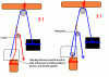
Fig. 9: A mechanical advantage system used to generate a large output force at point A from an input force of L2. Blocks B and D are the anchor blocks, and blocks A and C are the moving blocks. Assume that the lines are parallel, so that all four assumptions for basic mechanical advantage are met.
Returning to the reaction force calculations, the system in Fig. 4 had an advantage of 3 to 1 and a line pull of one third of the load. There are four parts of line at the anchor block, so the reaction force is four thirds of the load. This is a case whereby reeving the line through an additional sheave has not increased the advantage, but has created a reaction force greater than the load at the moving block. This is not unlike the climber belayed from below, where the reaction force is twice the climber's weight. Unless it were necessary to change the direction of the line, this is a case that should be avoided, since there is a higher chance that some component of the system will be overloaded, or that the anchor point may fail when a system is reeved to disadvantage. The system in Fig. 5 has an advantage of 5 to 1, a line pull of one fifth of the load and four parts of line at the anchor block. This gives a reaction force of four fifths of the load. With the four assumptions in place a pattern emerges where the line pull consistently goes down as the number of parts of line increases at the moving block. The reaction force, however, can be at most twice the load, but approaches a value equal to the load as more parts of line are added to the system.
The methods presented above can be applied to a wide range of situations encountered by the arborist in the field. The motivation in presenting these ideas is not that one will have a need for exact calculations, but instead that everyday tasks can be made safer by being aware of the magnitude of force generated when employing mechanical advantage. Using the estimate that someone pulling on a line generates a force of about their weight, the input line pull to a mechanical advantage system is known. Then the methods above can be used to determine the output load at the moving block (line pull multiplied by parts of line at the moving block) or the reaction force at the anchor block (line pull multiplied by parts of line at the anchor block). A quick calculation such as this might prevent the ground worker from using that four-inch white pine rooted in sandy soil as the anchor for skidding a log out of the back yard. On the other hand, the authors hope that these methods will make arborists reconsider some common practices, such as using a truck to generate the input line pull, or using in-line loops rather than pulleys when reeving for mechanical advantage. In the first case, one could easily generate a line pull that would push the system beyond the ratings of the lines and blocks in use. The second case dramatically increases the possibility of breaking the lines used to reeve mechanical advantage. With a line bent sharply around another, large amounts of friction and moderate loads, the heat generated and fiber damage from bending will quickly lead to failure, if not today then perhaps the next time the line is used.
--------------------------------------------------------------------------------
Back to the Top of the Article
--------------------------------------------------------------------------------
Western Chapter International Society of Arboriculture
235 Hollow Oak Drive, Cohasset, CA 95973
Phone: (530) 892-1118
FAX: (530) 892-1006
Understanding Mechanical Advantage.htm