


Navigation
Install the app
How to install the app on iOS
Follow along with the video below to see how to install our site as a web app on your home screen.
Note: This feature may not be available in some browsers.
More options
You are using an out of date browser. It may not display this or other websites correctly.
You should upgrade or use an alternative browser.
You should upgrade or use an alternative browser.
Bend radius for rigging
- Thread starter Keeth
- Start date
-
- Tags
- bend radius rappelling
Matias
Been here much more than a while
- Location
- Butte County
That sounds like a fat chunk of wood. Story time?i‘ve snapped slings twice, both were 3/4“ tenex and undersized for the load.
Daniel
Carpal tunnel level member
- Location
- Suburban Philadelphia (Wayne)
I’m not going to deny the block wasn’t choked up to the face. Looks like it is a pocket sling, and a branch collar was in the way.
I’m curious where the rope actually broke as it flung a short chunk away.
Slings held nicely, looked like a heavy piece (rarely work in oaks and constantly impressed by their weight). Wasn’t that a 1/2” line?
It’s not worth my time to argue but that wasn’t a new shiney line that broke and it was called…
A Humboldt wouldn’t have done that")
Criticsm of a cut or a technique as presented in this or any other video is not throwing mud... Crticism is a conversation.. throwing mud is attack on the person, not the technique. Pretty common around here. throwing insults when your argument can't stand on the facts, so personal attacks are all that you have left...wow way to fling mud and jump to conclusions.
interesting that Mark said the rope broke in two places... I'd assume at the knot/ marl (can't be seen in the video) and at the ring.. I broke a rope once when rigging heavy from a shackle instead of a block... bend ratio matters more when the rope is moving across the tight bend. I AM pretty certain that my rope wouldn't have broken if a block was being used. I bet a block instead of a ring would have been the difference in Mark's video too... With double whip tackle, that rope is moving twice as fast as when using a ring for lowering.. I have also seen a rope break in two places when it was over loaded. It's an interesting phenomenon that I have yet to understand.
If I was going to offer criticism of that particlar video, I would definitely say that the block was tied way to low. There was plenty of room to tie the block above the branch collar. The extra force in the poor placement of the block likely added enough force on the system to make the difference in breaking the rope. Remember when there is one extra foot of play in the block, the piece falls two extra feet... we need to recognize that a big top in leaf will have wind resistance that limits the acceleration, but a log doesn't, so every inch of slop in that sling counts x2, then apply Don Blair's formula to that 2x (which isn't exactly accurate, but even when adjuting for a gross overestimate in his formua) leaving a huge amount of added force for every extra foot of fall, and you have a problem... I prefer to tie the block tight and then make the cut as close to the sling as possible. I have never seen anyone else negative rig like that, though many likely do. CLearly mark did not do that in this video.
Another major factor was the poor performance of the groundman in handling the lowering line. There was zeo run. He was standing so far away and likely took too many wraps and was braced as if he was holding with all his might. Given that there was nothing but lawn below, this would have been a nice time to practice letting a piece run, and maybe run all the way to the ground. Looks like he had three or more wraps. Two would have likely been fine. Ive even seen big guys standing well away from the block let a piece like that run to the ground with one wrap. Perfectly controlled.
I don't like that rigging configuration when lowering from the bucket. I attached the lowering device to the bucket and then add a redirect block or ring/shackle usually between 8-25+' up the tree. That way there is no side loading and the rope man can stay right next to the lowering device (at the truck), which offers more control in allowing a piece to run, all while keeping the ground man out of the drop zone. If he needs to take a wrap off when the piece is hanging , he doesn't need to put himself inth e DZ to do so. It's faster and easier to set up, as I just leave the lowering device attached to the truck. And it doesn't require a sling that goes all the way around the base of the tree. And God forbid an inexperienced groundie gets sucked into the lowering device, he isn't going to get sucked into the tree/DZ and get killed in a struck by.
Last point of criticism is more about speed and efficiency rather than function and safety. That's an inefficient cut. When he had a pull line and loader to do the pulling there was no need for such a deep and wide notch. Cutting a 45+ degree notch half way through a big stem like that was a waste of time. He didn't even need a hinge really...
None of that is thrtowing mud. Those are all valid criticisms which I expect Mark would agree with, or at least consider worthy of discussion. My question is "why did he post it?" I suspect he broke that rope on purpose for the video. He even said he knew it was going to break. WHy would anyone set up a rigging system they expected to break? He certainly wasn't worried about the lawn. A little common sense goes a long way here...
While all the above are points to consider when setting up a rigging system, none of them have anything to do with the OP's suggestion that the rope angles on rigging slings can have a determental effect on strength... All those charts and trigonometry are meaningless and a waste of time when there are far more important considerations to study..
ps.. none of that math accounts for the rope making a turn on a round stem... nor does it account for the 2x drop in a loose sling which is a terrible suggestion... so stop the nonsense... If you're worried about it, just get a bigger sling and 1" block. If you're still worried about it, make sure the sling is long enough to use a cow hitch, which doubles the rope in a sling.. it's not rocket science. There's nothing wrong with overkill in rigging slings..
Last edited:
evo
Been here much more than a while
- Location
- My Island, WA
I’m not saying the setup wasn’t perfect.
I trust mark to assess the rope, and take the time to train the crew. Rope was the weak link and it broke.
The fact it broke in two spots is wild, I’d guess it was from the double whip getting pinched or somehow crossed up.
Neither of us were there
I trust mark to assess the rope, and take the time to train the crew. Rope was the weak link and it broke.
The fact it broke in two spots is wild, I’d guess it was from the double whip getting pinched or somehow crossed up.
Neither of us were there
Daniel
Carpal tunnel level member
- Location
- Suburban Philadelphia (Wayne)
He said he knew it was gong to break.. then he broke it.. Log lands perfectly flat on lawn at base of tree.... doing no appreciable damage, given that stump will be removed and lawn likely installed. That's as clear as it gets.. he did it on purpose or at least as test to see if and when an old rope would break. The fact that he then he posted it on instagram indicates it was done on purpose... Only he can say for sure.... what's up Mark? @Mark ChisholmI’m not saying the setup wasn’t perfect.
I trust mark to assess the rope, and take the time to train the crew. Rope was the weak link and it broke.
The fact it broke in two spots is wild, I’d guess it was from the double whip getting pinched or somehow crossed up.
Neither of us were there
Daniel I appreciate your contributions and closely watched your dynamometer videos back when you posted them. They are part of what stimulated my interest in the topic. The HSE report was a tough read and covered rules of thumb, even mentioned our Mark Chisolm. The reason I twigged to Dan's observation was it correlated with experimental data of mine and also no one brought it up before - (edit "and") winter is boring. I observe two effects. On a fresh tied sling it starts at a pretty small tilt angle, but then shifts to a larger tilt angle under load. Small angle amplifies the tension into the sling legs but encourages skidding on the trunk which absorbs hit, in my case reducing the hit x2. At the bigger tilt angle the force multiplication is reduced, all the way to x1 at 30 deg leg tilt. But if you start at the larger leg tilt angle you lose the force hit absorption of the skid.
Out of passing interest just trying to gather data of how slings orient themselves in -ve snubbed off (worst case) rigging. Hard data complements the analysis side. Could add some value to the industry.
My experimental sling legs started tied at about 5 deg tilt and ended up about 20 deg tilt after the snubbed catch.
Last edited:
TheTreeSpyder
Branched out member
- Location
- Florida>>> USA
i think:
The more a given rope organically resists bend, the more bend radius matters against maintained tensile capacity, the more harsher an impact it takes the deformity from pure linear column of force.
>>larger diameter host also distributes wear and frictions/heat.
Also where linear forces calc by distance of linear as we easier visualize,
>>but these radial calc by degree of radial of how much of 2 different dimensions are employed presently, and the impacts of change as it 'rolls'.
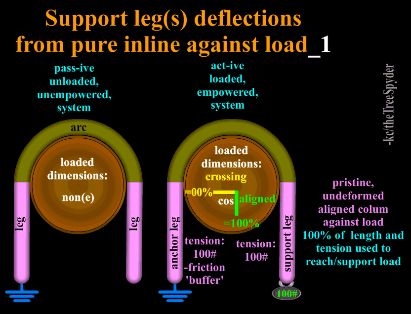
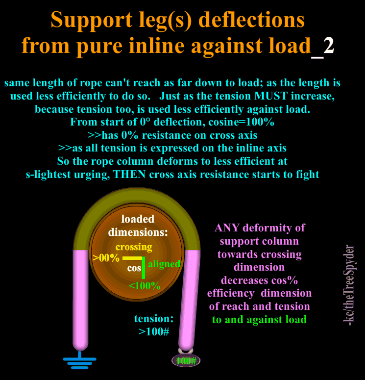
As we deform from cos100% pure inline column, pure 100% tensile rating is lost/decreases.
>>If cos drops to 86.6%(@30°), only that percentage of tensile is aligned against load for support(like if only used 86.6% of the material column to start/less capacity for same reach); and the material tensile (and reach) drop to that new sum total of availability, while actual physical length and tensile are maintained for the material, just not accessed to the chosen dimension; and there is some byproduct to the then crossing dimension.
This is what tried to show in dimensional changes of Tapered Hinge against sideLean vs. normal rectangular 'strip' hinge.
.
counter-intuitively in terms of length(then to all else):
between benchmarks of cos=100%(aligned dimension 0° deflection from benchmark column)
and cos=0%(crossing dimension 90° deflection benchmark column)
>>the sum of both dimension effects is greater than the given potential distance etc. itself against benchmark dimension.
This can give great range of choices and effects of engineering.
Also:
>>Where reach attribute is positional to reveal benchmark dimension
>>While force attribute is directional to reveal benchmark dimension (by contrast)
.
Material X has peak potentials of reach, tensile etc.
>>if 100% aligned to reach positionally against benchmark axis
>>if 100% aligned to bear directionally against load as benchmark directional axis
.
Crossing dimension is ante/non(e) of benchmark dimension
>>forming own references of sideward drift(in distance terms) and leverage(in force terms).
.
Bringing Time into it, is impact of change, of ever increasing speed (til'terminal speed of self-parachute) SQUARED. As beginning reference some offer 1' of drop is static weight added again , then per foot multiplied as go, but at about 8' or so(100# x8' > 900# at this point etc.); the actual is really outrunning the thumbrule too much. So, anyway looking in that direction of impact of change from the static measurement to go dynamic w/time factor.
.
Gradual de-acceleration (vs. sudden stop) is reverse, kinda 'snubbing'(use word often picturing a boat 'snubber' to reduce wave shocks etc.) out force gradually, but at co$t of friction to try to keep in range.
1st one compresses it's rubber hose as it expands too; it all worx.
 .
.

.
Peace
The more a given rope organically resists bend, the more bend radius matters against maintained tensile capacity, the more harsher an impact it takes the deformity from pure linear column of force.
>>larger diameter host also distributes wear and frictions/heat.
Also where linear forces calc by distance of linear as we easier visualize,
>>but these radial calc by degree of radial of how much of 2 different dimensions are employed presently, and the impacts of change as it 'rolls'.
As we deform from cos100% pure inline column, pure 100% tensile rating is lost/decreases.
>>If cos drops to 86.6%(@30°), only that percentage of tensile is aligned against load for support(like if only used 86.6% of the material column to start/less capacity for same reach); and the material tensile (and reach) drop to that new sum total of availability, while actual physical length and tensile are maintained for the material, just not accessed to the chosen dimension; and there is some byproduct to the then crossing dimension.
This is what tried to show in dimensional changes of Tapered Hinge against sideLean vs. normal rectangular 'strip' hinge.
.
counter-intuitively in terms of length(then to all else):
between benchmarks of cos=100%(aligned dimension 0° deflection from benchmark column)
and cos=0%(crossing dimension 90° deflection benchmark column)
>>the sum of both dimension effects is greater than the given potential distance etc. itself against benchmark dimension.
This can give great range of choices and effects of engineering.
Also:
>>Where reach attribute is positional to reveal benchmark dimension
>>While force attribute is directional to reveal benchmark dimension (by contrast)
.
Material X has peak potentials of reach, tensile etc.
>>if 100% aligned to reach positionally against benchmark axis
>>if 100% aligned to bear directionally against load as benchmark directional axis
.
Crossing dimension is ante/non(e) of benchmark dimension
>>forming own references of sideward drift(in distance terms) and leverage(in force terms).
.
Bringing Time into it, is impact of change, of ever increasing speed (til'terminal speed of self-parachute) SQUARED. As beginning reference some offer 1' of drop is static weight added again , then per foot multiplied as go, but at about 8' or so(100# x8' > 900# at this point etc.); the actual is really outrunning the thumbrule too much. So, anyway looking in that direction of impact of change from the static measurement to go dynamic w/time factor.
.
Gradual de-acceleration (vs. sudden stop) is reverse, kinda 'snubbing'(use word often picturing a boat 'snubber' to reduce wave shocks etc.) out force gradually, but at co$t of friction to try to keep in range.
1st one compresses it's rubber hose as it expands too; it all worx.
.
Peace
- Location
- Home of the New Jersey Devils
There's not much to this story. I was working with one of my brother's crews on a tree removal to help him out and met them on site. When it came time to chunk wood down, I decided to rig a couple of pieces to preserve the lawn because the stump was to remain 4' high. I asked for a larger rigging line since I was using 1/2" in the canopy. They brought me some old, crispy 5/8" line and I laughed. They Saif that the new ropes were not put back in this truck since this truck usually goes with a different chip truck. I decided to double-whip it for extra strength, but was not convinced it would hold. I wasn't worried because it was just grass. Told them to stay clear that this could very easily break since they couldn't lower much. It did break, but only in one place about 4' from the end. The rigging block was no where near 2' below the cut. Not a big deal or much to examine. End of story.
Daniel
Carpal tunnel level member
- Location
- Suburban Philadelphia (Wayne)
mkaes sense, but not to be dismissed and miss a learning opportunity.. Do you think the ring contributed to the failure?.. 4 feet from the end? was that the knot or would that be at the ring? Could the bend radius of the line on the ring do more harm that the DWT did good? These are the things I like to think about... I almost never DWT... But if I do in the future, it won't be with a ring...There's not much to this story. I was working with one of my brother's crews on a tree removal to help him out and met them on site. When it came time to chunk wood down, I decided to rig a couple of pieces to preserve the lawn because the stump was to remain 4' high. I asked for a larger rigging line since I was using 1/2" in the canopy. They brought me some old, crispy 5/8" line and I laughed. They Saif that the new ropes were not put back in this truck since this truck usually goes with a different chip truck. I decided to double-whip it for extra strength, but was not convinced it would hold. I wasn't worried because it was just grass. Told them to stay clear that this could very easily break since they couldn't lower much. It did break, but only in one place about 4' from the end. The rigging block was no where near 2' below the cut. Not a big deal or much to examine. End of story.
Last edited:
TheTreeSpyder
Branched out member
- Location
- Florida>>> USA
Nice;
Caught me by surprise until thought about it:
Doubled, double the strength figuratively, drops elastic dampening response.
>>does not invade (Max)'headroom' quite as deeply, so less elastic response in return.
Caught me by surprise until thought about it:
Doubled, double the strength figuratively, drops elastic dampening response.
>>does not invade (Max)'headroom' quite as deeply, so less elastic response in return.
Found a chunky example ignore the audio enthusiasm, you have to look hard to see the sling legs angle change
and this one the sling might have been loaded once already with the other codom but you can somewhat see the leg tilt angle under the second codom weight
we know this guy
And this one, grillon, no RW SRT spar cinch, cut away right at the dynamic moment but clear closeup aftermath
and this one the sling might have been loaded once already with the other codom but you can somewhat see the leg tilt angle under the second codom weight
we know this guyAnd this one, grillon, no RW SRT spar cinch, cut away right at the dynamic moment but clear closeup aftermath
Last edited:
ghostice
Been here a while
TreeSpyders's comment above #67 recalls a couple of videos - there was some really interesting info presented by Matt Follett at a recent TreeFund webinar this Tuesday - it will be posted soon on the Treefund Webinar website - look at the archived webinars in a week or two (writing this on 21-Mar-2024). He compared (among other things) block/ single ring/ double ring drop forces and tree harmonics etc. with hard data from new Quebec and British Columbia research projects. Not sure if everybody would have seen this. Also the above comment recalls for me a lot of rope info about rope breaks and bends in Mark Przekurat's video on Arborist Rope Bridges of all things. It provided (for me anyway) a different slant on potential rope failures and friction within the rope strands due to bends and fiber differences between different materials. Maybe have a look at these. Cheers all.
Addenda: Matt's work also looked at spar cuts and slightly open and wider open face cuts and the effect on both stem pushback and stem forward "yank" forces/ distances. Great stuff
Addenda: Matt's work also looked at spar cuts and slightly open and wider open face cuts and the effect on both stem pushback and stem forward "yank" forces/ distances. Great stuff
Last edited:
10 degrees tilt before, 30 degrees tilt loaded (by eye) (?)
this is the one alluded to earlier where a collar contributed to one leg's tilt - 3 different girths to see!
edit 4: the rig tip pulley, the stationary rig tip, the log pulley and the portawrap sling")
Everything I've managed to find shows distinct before sling leg tilt angles and after/loaded sling leg tilt angles. The after tilt angle is 20 to 30 degrees if the before angle was around 5 to 10 degrees. The after/loaded angles correspond to 40 to 50% increase of tension in the sling leg. Dan's math was right just the magnitude wrong.
This does raise the topic of sling strength which is it's own topic. I spotted a very tight tie on an X ring where the legs were directly on the splice. On a typical loose-eye dead eye the legs grab the two halves of the eye distributing the contact/bend load. Cow hitch has two legs per side seeing load vs timber hitch two/one. Whoopie (autocorrect!) loopy depends. Brummell-holed type slings it's twin strands or splice depending on style against join spot of brummel splice. You could see where same size cordage a loose eye dead eye in a cow hitch would easily offset the 40 to 50% and the full strength of the eye would be the limit. Bonner claimed 100% strength for brummels. And don't forget "one size up" as a start point.
this is the one alluded to earlier where a collar contributed to one leg's tilt - 3 different girths to see!
edit 4: the rig tip pulley, the stationary rig tip, the log pulley and the portawrap sling
Everything I've managed to find shows distinct before sling leg tilt angles and after/loaded sling leg tilt angles. The after tilt angle is 20 to 30 degrees if the before angle was around 5 to 10 degrees. The after/loaded angles correspond to 40 to 50% increase of tension in the sling leg. Dan's math was right just the magnitude wrong.
This does raise the topic of sling strength which is it's own topic. I spotted a very tight tie on an X ring where the legs were directly on the splice. On a typical loose-eye dead eye the legs grab the two halves of the eye distributing the contact/bend load. Cow hitch has two legs per side seeing load vs timber hitch two/one. Whoopie (autocorrect!) loopy depends. Brummell-holed type slings it's twin strands or splice depending on style against join spot of brummel splice. You could see where same size cordage a loose eye dead eye in a cow hitch would easily offset the 40 to 50% and the full strength of the eye would be the limit. Bonner claimed 100% strength for brummels. And don't forget "one size up" as a start point.
Last edited:
Matias
Been here much more than a while
- Location
- Butte County
The technical advisor at Marlow also claims that the brummel lock doesn't cost you any strength if the tail is fully buried, even in high modulus fiber.10 degrees tilt before, 30 degrees tilt loaded (by eye) (?)
this is the one alluded to earlier where a collar contributed to one leg's tilt - 3 different girths to see!
Everything I've managed to find shows distinct before sling leg tilt angles and after/loaded sling leg tilt angles. The after tilt angle is 20 to 30 degrees if the before angle was around 5 to 10 degrees. The after/loaded angles correspond to 40 to 50% increase of tension in the sling leg. Dan's math was right just the magnitude wrong.
This does raise the topic of sling strength which is it's own topic. I spotted a very tight tie on an X ring where the legs were directly on the splice. On a typical loose-eye dead eye the legs grab the two halves of the eye distributing the contact/bend load. Cow hitch has two legs per side seeing load vs timber hitch two/one. Whoopsie loopy depends. Brummell-holed type slings it's twin strands or splice depending on style against join spot of brummel splice. You could see where same size cordage a loose eye dead eye in a cow hitch would easily offset the 40 to 50% and the full strength of the eye would be the limit. Bonner claimed 100% strength for brummels. And don't forget "one size up" as a start point.
Muggs
Been here much more than a while
- Location
- Canuckistan
If this is true then it must apply to the hitch, where the rigging line is tied to the piece. Loading is same as the sling.Everything I've managed to find shows distinct before sling leg tilt angles and after/loaded sling leg tilt angles. The after tilt angle is 20 to 30 degrees if the before angle was around 5 to 10 degrees. The after/loaded angles correspond to 40 to 50% increase of tension in the sling leg. Dan's math was right just the magnitude wrong.
So if I tie onto a 100lb piece, then the rigging line sees 150lb at the hitch?
ghostice
Been here a while
In Matt's TreeFund video linked to above he mentions that really what matters most (echo Daniels comments above), in multiple trials with the same dropped piece of stem, is the height of the drop (i.e. distance from the notch up to the center of gravity of the piece being cut and down to the block or ring (makes sense - acceleration due to gravity is a squared dimension). Other thing about the slings that I'd add maybe is that a sling to a block say tied once tight to a stem (which will slip on the stem due to impact force (so 120 degrees is the magic angle where each side sees 100% of the load and above 120 degrees load increases sharply) is probably somewhat different than a block tied with a cow hitch with a better half, then around the stem again and another cow hitch, and so on 2 or 3 times till you run out of tail. With long tails and multiple trips around the stem, I've had much less movement down conifer trunks, even with some pretty big tops (even loaded with cones). Sometimes even gone for a ride (newbie groundies) but the block/ sling didn't move much at all. If you run the second "wrap" under the first, it'll hold the first wrap up more due to trunk friction? Maybe longer slings would help and also going back to using blocks rather than rings (more bigger rope friendly bend radius)? My (and some single malt's) two cents this Friday PM. Again, great thread. Cheers all.
Addenda: Maybe it's the single malt but what just popped into my head is my dear old departed Dad years ago saying that 80/20 doesn't really work for roofing . . . .
Addenda: Maybe it's the single malt but what just popped into my head is my dear old departed Dad years ago saying that 80/20 doesn't really work for roofing . . . .
TheTreeSpyder
Branched out member
- Location
- Florida>>> USA
Yes, in Big Al's E=M(static mass of resistance against achieving dynamic state of change)xC(dynamic state of change achieved)SQUARED
just as in total power in watts=wire resistance(nominal static against achieving dynamic state)x amps(speed of dynamic state achieved)SQUARED. It is the AMPS that kills, as the SQUARED quantity.
Usually see watts=vaSQUARED, but volts=resistance x amps, so collectively back to watts=resistance(as if mass)x speed(amps as if mph)SQUARED
>>found 75yrs before e=mcSQUARED evolvement in understanding as perhaps a broader interpretation at the end of the day.
.
Can't get away from the static nominal 'weight' against dynamic state of change(whether mass or wire resistance statically against change or anything else)
x dynamic state achieved anyway past nominal resistance SQUARED to be looked at as a consistent principle always and all ways in all things, cross verified here by physical and electro forces as facets to single central principle illustrated as happens in all.
.
Position and then Change in CoG is what always watch in all things mechanic too; these minimal principles seen/revealed in rawness and magnitudes of tree work, then can see in all things, even tho usually more subtlety. Like tree intensity of work and risk as a magnifying glass for what happens normally in all to be observed. Doc Shigo invited each of us to not just work trees, but touch trees, these things are right there too; to be touched hear too..
.
cos:sine are the value pair of aligned vs. crossing dimensions as pair of non(e)s to each other, but yet complimenting each other to sum of the whole. One of the mnemonics is sine as drift of sinus , and co-sine as the COmplimentary to sine. i always looked at it as co(lumn)sine of support and reach applied to/against load force dimension; and sine as the byproduct(from a support type of view) sin(e) across. Support efficiency of material potential is cosine% to me, as how much of the material potential is available to work on benchmark axis for reach against and support against dimensionally. Leverage efficiency of potential is sine%, so leverage theory is bastardization/reverse of support theory to me; a byproduct of support turned around and examined if can capitalize that dimension effect too(as well as support) like Tapered Hinge. Everything is defined/ruled by these aspects of static resistance against dynamic state, dynamic state achieved anyways SQUARED, CoG, cos/sine.
.
Everything matters, even that slips, stretches etc. has friction that taxes against force total, like pressure cooker relief valve decreasing peak steam force. Math can give full accounting balance in all things, if imbalance the change of motion etc. makes up the difference mathematically to balance equation, until satiated/in balance again(sailor wandering from port to port seeking mate theory, as till the same!!).
In positioning can see the aligned vs. not aligned/crossing dimensions of cos:sine value pair as aligned reach:crossing drift%s and in force terms cos:sine value pair can be taken as support:leverage%s. Raise in tension for same support against same load is because not all the tension force of material can be used against load dimension(just as not all length of material can be used for reach in that aligned dimension, to the same ratio cos:sine pair), drop in cos is a drop in support efficiency in that dimension(and reach in that dimension), and promises an increase in byproduct of leverage from increase in sine on the crossing dimension to the sum total of the whole, yin/yang; at the corner of East meets West hear.
.
Modeling these in clean simplicity of pendulum swing for different view/facet of same rules: the hang position is the unique, single, organic COSINE; the extreme of the swings as SINE to each side. i always look for the relaxed organic state as referenced, cosine; a unique, thus benchmark in scenario.
Taken from simple horiz motion of pendulum/swing to vert in simplicity of spring by contrast; yet still the same: the relaxed , unique, center of motion position/where the 'marble' 'organically' rolls on own as happy balance chases, is cosine and the extremes of extensions and contractions is sine to now vert 'sides' of high and low. Greatest speed is thru cosine organic position calling home in each, and zero point non(e) of that speed is the breathless stall before return FELT by all in child's swing before speeds towards bottom of swing pure cosine speed and reach, to then be going uphill to other side zero speed point and zero downward reach compared to rest of movement. For it is all the same everywhere.
Rope, as Greek support column, as all; only peak efficiency at UNIQUE cosine of zero drift from organic aligned position of minimal reach against load. Everything is a displacements against(key terms) freespace or force against another in occupied space. Force is unachieved distance resisted(in same dimension/cos) or compressed(or diluted) distance(leverage/sine). So force(unrequited distance that could have been)is always intertwined with distance as reciprocals/compliments to the sum of the whole. Sine potential positions are NOT unique, ONLY cosine is the true defining unique organic in this model; thus benchmark for rest.
.
Truly, truly may take out very many 'birds'(of not understanding, flying around seemingly w/o pattern) w/single stone of these really few principals; per ratio of magnitude of things can hit.
.
Seen Brummels etc. quoted at 100% too, i do stick with anything but pure aligned has some loss/co$t against pure pristine column, as a conversion co$t of dimensional change type model. Brummel does offer 2 solid legs to divide load around host, but then a 'node' swell of splice at Y junction to Standing Part, softly slanted and then softly tapered for least impact of change and draws individual threads more to aligned column against load as can.
>>vs. a short, fat, sudden impact of change of short splice; that does NOT draw it's fibers at splice towards inline column, but rather across(as races to make around Standing Part so crossing more than long splice threads impact of change (whose impacts of change can be softer as more column than crossing vs. short splice).
.
Peace
Dan Thornton
Participating member
- Location
- Smithsburg
I apologize that my diagram of the highline forces sent this discussion in the wrong direction, I'll take the risk to add another diagram. Corrections will be much appreciated.So if I tie onto a 100lb piece, then the rigging line sees 150lb at the hitch?
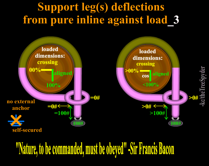
First, rigging forces are NOT like highline forces. That is because the rigging line goes THROUGH the hitch. The hitch is bending the rigging line. The rigging line is not trying to bend a highline. The following diagrams show range of 'bending' that we introduce, depending on where we set the hitch.
Second, because the hitch is able to slide along the rigging line and because the rope is able to stretch, the angles try to get as close to 120 degrees as possible.
Here are three diagrams showing the range of "normal" tension in the lines at the rigging points. At least, this is how I visualize it. Since I always try to simplify everything, I'm certainly missing something here.

If the hitch were not a hitch at all but a Pinto pulley, then the tension on the pulley would be a theoretical zero to twice the load. Zero happens in the first diagram above when the bark friction dissipates all the force. (Some arborists get close to this 'zero' when they wrap the log two or three times then connect back to the rigging line with a carabiner.) Twice the load happens in the third diagram above. In that case, on a Pinto pulley, it would act just like any pulley situation, with twice the load weight transferred above the pulley. Since we do use rope and not Pinto Pulleys, a lot of the extra force at the hitch is transferred to internal stress in the rope.
That's how it makes sense to me now.
TheTreeSpyder
Branched out member
- Location
- Florida>>> USA
Like a battery to circuit, the wiring of rope and host are unloaded until 'lit' by the initiating force of the load, then trace geometry. Electronics can give changes and commands by circuit, geometry is the mainframe of engineering both mechanics and position. SPart(Standing Part) is the linear input/gas feed empowering the arcs of change/sliding cos:sine at the co$t of linear to radial conversion.
.
#'s reference picture in previous post above
>>not the pics added later to this post..
#1 can go around host 3x (or more a/n) usually and present no cross force as link/secure to SPart(especially if accidentally laces thru one of the Turns) , this is called Tensionless Hitch(no cross tension).
>>the more the cross force shows against column of SPart(w/less Turns) as sole support leg to give deformity from pure support column, the lower the cosine efficiency% of how much of tension(as an attribute now of the material) is expressed to support column against load dimension. Same for the attribute of length/distance, at same cos rate..
#2 Has deformity across against the sole support column of SPart against load, determining how much of tension and length of material is applied against load dimension. °This is a single leg of support.
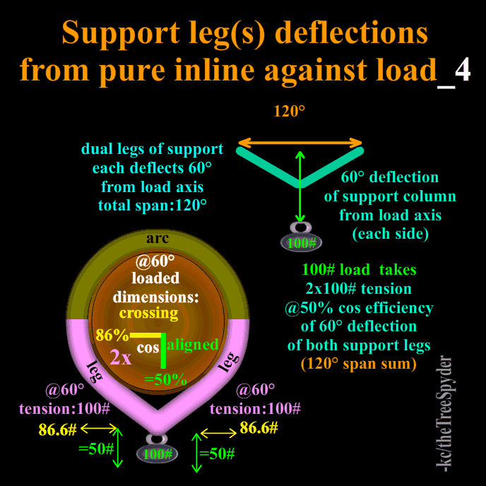
>>IF dual leg of support like both ends of eye2eye as supports; not single leg of support eye2eye choked, THEN at 120°; have 2xLegs of support of 60°, deflections each from load line, so therefore cosine% efficiency of support is 50%, then x2 legs; YES calc each leg @ load tension x50% is 1/2, 2nd leg completes to sum of load.
#3The SPart input feed is = to load against, everything else is geometry, eye gets.than can only pass at most 200# if 180 bend thru it from the SPart to BackTurn type
.
edit/adding:
The same strategies work for distance and force etc.
But, they work in distance per positional attribute of material
>>as they work in forces per directional attribute of force /sender
or from other perspective per directional attribute of material/rcvr
>>either/or works: because force displaces against equal opposite to cross-verify with
>>whereas distance only displaces against freespace
.
#'s reference picture in previous post above
>>not the pics added later to this post..
#1 can go around host 3x (or more a/n) usually and present no cross force as link/secure to SPart(especially if accidentally laces thru one of the Turns) , this is called Tensionless Hitch(no cross tension).
>>the more the cross force shows against column of SPart(w/less Turns) as sole support leg to give deformity from pure support column, the lower the cosine efficiency% of how much of tension(as an attribute now of the material) is expressed to support column against load dimension. Same for the attribute of length/distance, at same cos rate..
#2 Has deformity across against the sole support column of SPart against load, determining how much of tension and length of material is applied against load dimension. °This is a single leg of support.
>>IF dual leg of support like both ends of eye2eye as supports; not single leg of support eye2eye choked, THEN at 120°; have 2xLegs of support of 60°, deflections each from load line, so therefore cosine% efficiency of support is 50%, then x2 legs; YES calc each leg @ load tension x50% is 1/2, 2nd leg completes to sum of load.
#3The SPart input feed is = to load against, everything else is geometry, eye gets.than can only pass at most 200# if 180 bend thru it from the SPart to BackTurn type
.
edit/adding:
The same strategies work for distance and force etc.
But, they work in distance per positional attribute of material
>>as they work in forces per directional attribute of force /sender
or from other perspective per directional attribute of material/rcvr
>>either/or works: because force displaces against equal opposite to cross-verify with
>>whereas distance only displaces against freespace
Last edited:
Clarification. Worst case I refer to is best of worst case -ve rig snubbing i.e. most compact tight setup for shortest free fall. This is I believe generally accepted as base case in testing. Pretty obvious it only gets worse with longer free fall so proving it experimentally has been a lower priority based on what I've seen.
I agree with Muggs on application to a hitch.
I should explain that long eye/splice segment and two legs are considered co-planar in my analysis in order for the standard sling angle diagrams to apply. You have to ponder a bit to visualize it to the rig tip. First idealization is rig line/sling segment straight down side of trunk. Don't happen exactly. Second idealization is sling legs perfect circle around trunk - don't happen. The rig line force vector (to which the sling self aligns) points at about 20 degrees out from vertical IIRC HSE then ends up down the trunk with the peak load out at that 20 angle. The sling legs transform into this weird curved/angled shape partly following the curvature of the trunk. In viewing the videos the dynamic "angle shape" doesn't seem grossly different than the post-catch statically hanging angle shape - that's the 20 or 30 degrees off horizontal as viewed perpendicular to the 3-legs-in-a-plane which the camera views aren't, they're usually at some other viewing angle but we an use our brains to estimate the correction for viewing angle.
I agree with Dan that the "pull start the trunk" configurations make imbalance in the sling legs though quantifying it would be a real SOB to do with the weirdness of the geometry and unestablished self-settling/adjusting effects from the impact load. Mild off centering I'd venture say 10% higher in the unlucky sling leg.
I may have been incorrect in the Bonner quote. It might be brummel maintains 100% of Single Cordage strength i.e. there's two full pieces of cord at work but only strength of single.
A marl or half hitch is slightly different in that the exiting rope to the girth helps hold the marl from tweaking its shape in the familiar way. The girth at the end does the sling leg angle boogy though.
ps Can anyone come up with more videos? I'm not on face-twit-gram etc. No offence I'm a luddite.
Last edited: