DWT

Mark Chisholm

Administrator
Administrator
I sometimes take advantage of the mechanical advantage available with Double Whipped Tackle. I was wondering if anyone has calculated how the load will effect the anchor points when the rope angle is changed?

More specifically, if you spread the anchor points in the tree (or trees) to create 120*, 90*, 60*.... and so on. I would also like to see what equations are used. Anyone?
 
If i understand the question correctly; i think that the loads on the spread apart anchors that support the 2/1:DWT will be determined by the angle created, in the line, in the same numbers/math as speedline support loading. Also, maximum power of 2/1 will be in parallell lines, so the wider/unparallel lines have less MA?

i think both would be calculated like sling angles , only the load pulls down, rather than crane pulling up, but same loaded angle of pull function. Like in Blair's "Arborist Equipment" pp175,176. And Clicking "Slings 6.7" in OSHA Crane Rigging Manual and AirForce Crane Certification Manual on page 55. (Great Links on certification training for hadling load forces).

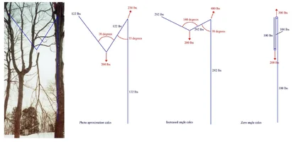
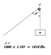
Therefore as the load lowers the angle that determines the load on support anchors will change, as the angle in the line gets less obtuse (angle going from support-load-support), the load angles on the lines/anchors change and load on anchors is reduced. So, as the line is first taking the load impact, it is also most leveraged; whereby these higher loading factors at the same time compound each other; making tearoff about the most hazardous time?

The power of the DWT can give more support, as well as pretightening, helping 2 ways. Also, offer different steering properties (to center of anchor's support,still) be tag lined easier between the 2 points of support. If the control leg, deflects to the ground, that anchor will be more loaded, and the legs of lines angles of pull would matter on that support too. i like a 3/1; as 'odd legged' systems are retreivable and pull to a favored side. With no pulleys on supports, sweat lines in well, giving super pretightening before loading, and more available support x friction for control, can take 4 legs of line though!

Or at least that is how i always looked at it!
 
Hi, guys;

What I've done is combined 2 posts I wrote elsewhere
and put them together here. This post would otherwise take me hours to write. Remember, this is nothing more than applied trig and statics, but it is enough to be taken as serious and correct.

One needs to remember the angles are measured at the load.

T(1)=[mg×(cos@2/sin(@1+@2))]

T(2)=[mg×(cos@1/sin(@1+@2))]

where:
T=tension of the rope

mg=weight of the load

@1= theta angle mg makes with the rope towards the upper left rigging point T(1).

@2=theta angle mg makes with the rope towards the lower right rigging point T(2).

/=division symbol

For the block located at the primary rigging point:

How one starts is sum(add) tensions from the vertical and horizontal components of each leg of line.

T=tension of the line.

sum=add

x=vertical component

y=horizontal component

The vertical components of each leg are:

(sum)[Tcos 180° + Tcos 270°] = T(-1)+0=-1

(sum)[Tsin 180° + Tsin 270°] = 0 + T(-1)=-1

T can represent any line tension which is =
to the weight of the load. I chose 1 for simplicity. It needs to be understood T is the same for both vertical and horizontal components in this example.

What we're interested in knowing is the tension of the sling attached to the lowering block. This means we need to know the resultant tension along with the angle the resultant tensions make with the rigging block sling.

To do this we use the pythagorean theorem
to sum the 2 components we found earlier.

R=resultant force or in this case tension.

^2=the power of 2 or squared

sqrt=square root

The formula we use to find the resultant tension is R^2=x^2+y^2 and R=sqrt(x^2+y^2) Therefore:

R^2=(-1)^2+(-1)^2

The square of a negative # is a positive #.

R^2=1+1

R^2=2

Take the square root of both sides of the equation to get:

sqrt(R^2)=sqrt(2)

The square root of a square, like that of R, is simply R. Therefore

R=sqrt(2) and sqrt(2)=1.41

Therefore R-the resultant force or tension- is 1.41. This is the tension of the sling attached to the rigging block.

To find the angle the sling makes due to the tensions in the line, take the inverse tangent of the vertical components divided by the horizontal components.

tan^(-1)[(-1)/(-1)]=45°+180°=225° which is a 3rd quadrant angle because both x and y components are negative. Otherwise, a rope which makes a 90° angle through a block will make a resultant angle of 45° which is an equal distance between the 2 legs.

I consider the torque produced by the x-component of the lead of the line or secondary riggng point to be the dangerous part of this particular rig. This is how the x-component is found.

Tcos@ = x-component

Joe
 
I'm not sure about this 1 but here she goes.

To determine an acceleraton where the tensions cause the load to move upwards, try using this:

T(1)+T(2)-mg=ma

T(1) and T(2) = the initial tension in the line. This is the same mess I went through to find the resultant tension for the pulley in my 1st reply.

Sum x-components:T(2)cos@(2)-T(1)cos@(1)=ma(×)

Sum y-components:T(1)sin@(1)+T(2)sin@(2)-mg=ma(y)

Resultant R= sqrt((x)^2+(Y)^2) (the components)

inverse Tangent @=tan^-1(@)

tan^-1(y/x)=angle @ makes with the x axis.

Try puttng that in a pipe and smoking it. :)

Joe

I'm glad I threw my pipe out.
 
cough, cough, blech...

that smoke is too thick, Joe :)

Thanks for doing your usual Joe-Job with this but I don't have a graphing calculator to bring along when I rig. I wonder if that can be distilled down to a rule of thumb?

When we set up rigging, especially when we get complex, using DWT, the loads move all over. Then we go and pull the load at an odd angle, that makes for more complexities.

Keep up the good work, Joe!

Tom
 
Tom: I realize what you're saying. The 1st post equations are 2-dimensional and static. The 2nd is 2-dimensional and dynamic. In reality, all the equations are 3-dimensional with the z=component being zero. They are better than what is out here published in our industry that I'm aware.

These aren't ment to be taken into the field and applied while we're working. They are here for us to use to get a better idea of what to expect in the field after they have been applied on paper. I doubt if many know how to use these to their benefit. But, the math should stimulate some thought.

Joe
 
I probably shouldn't be posting this stuff. I edit so much initially I get a headache. I edit because I'm usually wrong about something if not outright wrong about what I posted.

Joe
 
I wanted to attach an .xls file so people could play with a formula i set up, but it will not attach unless it is a picture. If you want to download it, go to
www.verticalpro.net/dwtcalcs.xls
As has already been stated, no one should take a laptop to a tree. But being able to visualize here how the forces act on a tree will help you to understand the real world a little better, recognize potential hazards and climb and rig safer.

Dave
 
Dave;

The third drawing of your third attachment ('more still') shows 300 pounds at the pulley. But that is true only if the left leg of the line is attached to the same anchor as the pulley. If the left leg of the line is supported independently (as it appears to be in the drawing), then the anchor that supports the pulley sees only 200 pounds, 100 on each side of the pulley. I haven't worked out the math for the other drawings, but the same concept would be true for them as well.

Mahk
 
Dave has the idea about how to use equations. I have seen a variation of the equations figured for the dwt in an article written by Graeme McMahon. The article was published in TCI magazine titled "Opposing Pendulums". Graeme did a very large removal which required nothing fall from the tree. It was a very interesting article. Graemes' team used a laptop computer throughout the removal. The equations were plugged into the laptop and showed him line tensions. When he found the tensions in his lines, he measured and cut his pieces accordingly. There was more to that article than I describe here. The 2 equations weren't the only equations used to help determine line tensions. But the article shows when the situation warrants managing motion, a laptop or calculator can be an essential tool for the arborist.

Joe
 
Back
Top Bottom