Nerd Alert

Did you vibe code using functional specs into an english language interpreter, or did you instruct it "make/code me a cycling picture frame display like X product? Using blah blah esp32 board and whatever else. Did it do the wiring/cct layout too? I've heard of such end to end AI tasks.

I'm too luddite to have executed any AI tasks yet. or chicken.


If someone expected me to learn/write with a jpeg etc library, interface and manage it successfully and also learn/interface the graphics card/driver interface and get that to work bug free I'd respectfully back down and say the mountain's too big for me to climb. Kudos to making AI work!
I have a pretty healthy understanding of the hobby, I just can’t write the code. So basically I pick the HW I want, in this case the display and the ESP32, I wire it up based on datasheets (though Claude could definitely help here if I didnt understand the datasheets or wanted to be lazier) and then I tell Claude what I want it to do in plain English.
Claude wrote the python scrips to pull all the images together and then writes the code that I load onto the esp32, again just prompting with all plain English text as if you were speaking to a person.

I rely on AI heavily for all sorts of projects like this. Many years ago I was heavily into this and could even struggle through writing simple arduino code on basic stuff but it wasn’t enjoyable and the level of finished “product” was rudimentary at best. Now days using Claude I have a pretty advanced home automation system, I have fun projects like this and I have actual useful stuff too like a fan controller for my truck (which has been converted to electronic fans from the factory mechanical fan) and you know what? I’m having a great time doing it! It still takes work and understanding. I’m not some idiot pounding the keyboard “duh Claude make this” and ending up with really nice finished products. It still takes lots of time and work on my end.

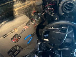
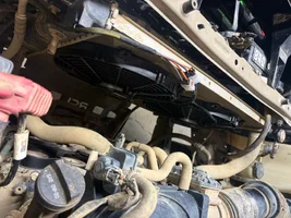
This is the fan controller, it’s probably the hardest thing I’ve vibe coded. Not only does it control the fan based on speed, temp, AC and load but it gets its data from factory CAN-bus data by interfacing with the Toyota ECU which it figured out how to interpret after watching logs.
 

Attachments

  • IMG_8321.webp
    IMG_8321.webp
    89.6 KB · Views: 6
  • IMG_8295.webp
    IMG_8295.webp
    244.6 KB · Views: 6
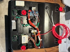
Four cct boards + display! What were the 4 boards? The diagonal chip looks like a cpu. Did you raw parse the can bus or was there some library support? I assume read only to get the temp etc, or did you have to request it? Do you control a fan's electric power or an electromagnetic clutch like for ac?

I've only done one arduino project, my woodstove air control which I largely copied from a guy on github. It's linked somewhere here on the buzz. I was beginner level, uno, and I constantly ran into code memory limitations. I data logged to an SD card too.
 
The diagonal chip bottom left is the Atmel 328p, that’s the arduino. Top left is the CAN transceiver, right side is the opto isolator [near screen] for the output to the relay (which can be seen in the other image) and then there’s the 5v regulator on the right side further and on the left side is another optoisolator that was originally used to sense the AC clutch but it turns out that Toyota monitors the inpediance on the clutch coil and sensing it fucked that up so the state of the AC is determined by monitoring system pressure pulled from advanced Toyota-specific CAN data.

Edit**** this placement description is with the screen facing towards you. I don’t know why my photos rotate when they upload.

The speed and coolant temp is pulled from the basic ODB data with a CAN library I found. the ac state was much harder since it’s not in your basic OBD packets. What I did was capture a bunch of raw data to find the exact bit and then it averages that reading over 5 seconds and watches for a sudden spike.


Getting more into the system overall- it disables the fans above 57mph because the amount of airflow at that speed is more than the fans can create anyway and it also has a button to temporary pause fans no matter whats commanded in case I’m driving through water (you don’t want your plastic blade electric fan spinning while they’re partially submerged). Also you can adjust the set points on the fly without having to do any coding or reprogramming.

And again, every bit of this was vibe, coded: “hey Claude, here is some raw data, in hex which i dumped from my truck. Here is the times I turned the air conditioner on and off. Please discern a way to tell on verse off.”


Install process, that is a GM 10-pin connector. In the glove box I have the same connector with the relay trigger shorted directly to ground. In case something fails some day I can unplug the whole tray, plug that in and have the fans running with no logic so the truck can be driven on down the road.
IMG_8307.webp

Test rig with baby screen and plugged into the OBD2 port (and only simulating the fans with an LED) while i got it dialed in
IMG_8236.webp

60A breaker and the relay. I chose this relay cause it has an internal flyback diode which is required since it’s a very large inductive load.
IMG_8640.webp

All this to drive these SPAL 12” electric fans (factory is a single mechanical fan). Puller type “quiet” fans aka S blade fans pull about 2600CFM combined.
IMG_8639.webp


One more truck project, since I like talking about it. This one controls the rear e-locker. It came equipped in my trim level but the restrictiveness of the factory system is crazy so i did away with that crap right away. But you can’t just flip it on or off cause it’s a modern Toyota, you have to pulse it at 100hz so that’s what the system there does. It also has a cool little display and uses the factory button and stuff. This is the last one that I actually coded myself, even then relying heavily on other people’s work and googling but not ever vibe coding. I enjoy the way I do it now, before it was out of necessity and not actually a fun process.
IMG_8210.webpIMG_8233.webp
 
Last edited:
My hat's off to you! Impressive and cool.

Automotively, my truck had an intermittent hot ignition feed during cranking, so I wired a hot crank voltage push button with a voltage calibrated LED sensing right off the coil terminals, so I could confirm hot V application in the face of battery voltage, cranking load and system-not-faulted out. The actual application was via a relay next to the coil. Coil, hall sensor and distributor with vac advance! With Weber carb, crank hot coil V and electric choke it was crank 1/2 rev fire up like clockwork :)


Prior to that I wired in switch bypassable opamp signal offsets to tweak IIRC MAP and TPS sensors into a 90 integra cpu for emissions testing. They were right at the specs boundary so I centered them. Guy muffed up the testing so I never got to see if effect was present. No discernable difference in roadability.
 

New threads New posts

Back
Top Bottom