2 Handing a Rig Test

TheTreeSpyder

Branched out member
Location
Florida>>> USA
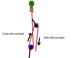
2 handing is a term i've coined for grabbing at a 2nd place in rig, to pull at it, in the opposite direction that you pull the standard end from. This i've theorized aloows you to use your pull towards target, and it's usually wasted, Equal and Opposite pull. This takes that E&O/ usually wasted force, and 'recycles' it/ turns it around to aid in pulling on the target load too.

i've tried to show this principal working in various forms ove the years, most recently in Nick's "Redirect at base of tree for easier pull?" thread and a thread called "Force Relationships".

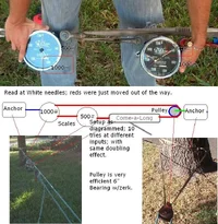
We've talked theory; these are the trials; will await rebuttal actual trials. i used a comealong putting out 500#; to show an exagerated version of a man's pull from both ends onto target. i contend, that the zrig inset inside the ship's rig is the same, and that that whole rig, itself could be 2 handed.

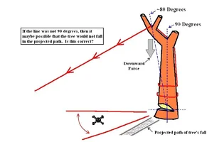
Force is force, this shows how more can be put on your side, easily available by pattern; also, how that can be set to stand against your efforts! It is not where the pulley is on load that gives the 2/1; but how many legs you pull vs. how many that pull on the load, that gives the multipliers, even in this simplest of examples.
 

Attachments

  • 35377-2_Handing_Proof.webp
    35377-2_Handing_Proof.webp
    140.1 KB · Views: 232
So what you are doing on say a 3:1 Z rig is one hand is pulling the tail and the other pushing the second leg?

I get a headache around number 7 in that flashy thing you made, plus it keeps changing when I'm trying to check it out.

I've put bit of a sketch in, am I on the right track to your theory so far?
 

Attachments

  • 35455-3to1.webp
    35455-3to1.webp
    10.8 KB · Views: 147
Ya have to do it, try like a tie down that the z rig is long enough that you have arms stretched apart, and they pull towards each other, each bracing the pull off the other.

Usually, we pull against the foundation of our own weight standing on the ground, or we pull against our free hand grabbing an outside anchor. Instead, put what you pull agianst to use; pull against the other hand that is heloing pull on system!

We only pull, not push rope; for it is a tension only device. The Flash viewers i maid, you can click the numbers at the bottom to jump to that scene. So, you can click 7 when it moves to 8 tooo fast, and it will replay 7 for you etc.
 
So you have tested this with scales and if you stand between the two pulling them together you get a larger force output than heaving with 2 hands on the one tail (final end)?

Hmm, if that's the case that's weird. You would assume that heaving on the third leg (3:1 MA) with both hands would give a higher output.

I'll have to some how rig this up and try to measure it.

Got any vids? Ha, just kidding. But I can see why people would argue till they see the real figure "live" ... people like me that is.

Are you sure it's not just you, due to your strength in pulling two ropes together?
 
2 100# pulls att he tail is better, as i stated in scene 4 (click the 4 on the bottom of the viewer) of 2Handing .

A while back when trying to show the Mayhem Puzzle i maid; i tried to also show that a 3 over 2 pulley system was more descriptive of ZRig potential. Glens said that added my usual confusion /forum/images/graemlins/blush.gif. But, going on witht hat train of thought; what i meant was that a 5/1 could have 4x or 6x pull on anchor. Also, that it made more sense expressed as a 5 over 6, to show the forces on each end, especially if inset inside another system or deciding which end of the system you wanted to use for power!

The shortcoming seems poplular, to not recognize the Equal and Opposite operating/usable force. Ekka it is better to have 200# pull x 3; than the 100# x 4 i'm speaking of, of course. But, once again,the Equal and Opposite part of the marriage of forces is left out in that view.

For the 200# input you speak of, requires a 200# equal and opposite force of bodywieght and or hand/foot hold, for a total use of forces of 400#. The 2handing i speak of; places 100# at the 3x postion, and gets another 1x at it's 1x position (at top of Zrig system)from the Equal and Opposite force.

Removing the bodywieght, where all of it is hand pulls or comealong use, shows this better. It would take 2 100#pulls (by 100# capacity springs, comealong etc.); and an anchor taht resisted the 200# Equal and Opposite in your scenario, to get 600#. But, in 2 handing, i could take the same comealong/springs/handholds and place their Equal and Opposites to pull on the 1x position (of zrig) to get 800# ansd not need ahother anchor to do it.

The only differance is i recognize the Equal and Opposite force, and put it to work inside the system pulls, rather than opening the system more to pull on another anchor, 'wasting' that force that could be put to work.

If the comealong/spring/person weighed 100#; then the comealong/spring/person would only have to supply/ be tightened to 100# more pull for same effect, and anchor only would get that amount of pull, for your 600# exiting top of system. Or, in 2 handing sense, i could take that 100# pull to anchor (from tightend device) and set it at my 1x pull position, to get 700#, instead of 600#.
 
2handing%20force.jpg
 
No Problemo; i'll try to bring up some other interarresting tests...

i've maid a Force Relationships Page from these drawings. If'n ya look at them; the pattern presented is that we fold the Equal and Opposite force back on itself, for more power; like our DdRT. Like the picture above, we close the 'circuit' of the system, to conserve those forces; rather than having the system open, and allowing the potential of the E&O force to escape working on target!

To me, this maximizing strategy is inherent in many things around us; like a simple faucet handle...
faucet.GIF


i think the trees know this; in their world either the branch feeds the tree, or dies and falls off, and feeds the tree! It is we, that take that circle/ circuit flow of recycling energy, and break it open, to a linear/non circle/recycle (state) of leaving the branch so it feeds the tree, or removing it from the tree and site so it doesn't feed the tree as choices. Our actions give this more open system/leak of E&O re-source(like not 2handing when possible) beyond self equalibrium/correction range of tree health resources. For the more of the tree's way honored, the more Nature force captured in cycle; like a larger aquarium being easier to care for. In it's biosphere; it either wins or it wins; no real loss. This i think is part of it's size it accumulates and maintains larger than any other, then lives onger too! But kinda a pairallell use of the force (branch growth) and it's Equal & Opposite (branch death) capitalized on in this continuim/longevity/circle!
 
i maid this for using some of this for support strategies. This shows other things that can be tested with Dyno. Though usually ya need another scale to measure input force, then read output force on Dyno..
 

Attachments

  • 36262-2handingorinsettingZrigs.GIF
    36262-2handingorinsettingZrigs.GIF
    55.3 KB · Views: 74
Tree Spyder:

I like all of the thought and time you put into this. I like the "Back leg support" theory.

If I used your "back leg support" theory while felling a tree, are you saying that there would be more torque on my pull if I tied off at the bottom? (See my first illustration).

It seems to me that it would be crutial to get that line to follow a vertical axis (90 Degrees). If it were not at 90 degrees, then there could be disaster. (See my 2nd illustration).

What do you think?
 
[ QUOTE ]
If I used your "back leg support" theory while felling a tree, are you saying that there would be
more torque on my pull if I tied off at the bottom? (See my first illustration).

[/ QUOTE ]
He might be saying that there would be more torque (we all love Kenny and his zeal, but sometimes
translating the result is a bit of a work of art). As a point of fact, there would be no difference in
the amount of torque presented to the hinge fibers. Tie the rope off at the top; set it there with a
running bowline; drape it over the point and secure it to the stem below; all provide for the same amount
of torque all else being equal.

[ QUOTE ]
It seems to me that it would be crutial to get that line to follow a vertical axis (90 Degrees). If
it were not at 90 degrees, then there could be disaster. (See my 2nd illustration).

What do you think?

[/ QUOTE ]
Again, no real difference between directly attaching to the first contact point or lacing it down the back,
side, front, whatever.

Lacing and securing low has some advantages in certain situations, to be sure, but I feel they mostly
pertain to situations where climbing-avoidance is desired and tree form would make a running bowline
impractical. To its disadvantage, the system places higher loading on the upper contact points.

In your second drawing (JPG is perhaps the poorest choice of image compressing options for just about
anything besides "photographs"; GIF would suit you better [PNG the best] in terms of file size and quality),
sorry; anyway, the formation of the hinge and faces is what's going to determine the direction of fall.
The rope really only makes initiating the fall easier when you're pulling so much in line with the direction
of fall. It would help in overcoming a moderate back lean, too. If you want to use a rope to actually
do much in terms of assisting the direction of the tree as it's falling you'd likely be tensioning
the rope in directions anywhere ±89° (think: counteracting a side lean, etc.).

It doesn't hurt to put a tag line in a tree about to be felled, but to do so as a matter of course is
somewhat misguided IMO.
 
Quote from Glens:

In your second drawing (JPG is perhaps the poorest choice of image compressing options for just about
anything besides "photographs"; GIF would suit you better [PNG the best] in terms of file size and quality),

Thanks for the tip! /forum/images/graemlins/grin.gif
 
Just a quick(?) diversion:

I scribbled a small image with a stick man, some (smoothed) text, and some colored shaped areas: one each of a red solid-filled "circle", a green "sprayed" area, and an orange "brushed" area. I saved the original small image in both PNG and JPEG formats, named "scribble.png" and "scribble.jpg" respectively.

Then I displayed them side-by-side with a magnifier window below each respective one. Finally, I grabbed a screenshot of the ensemble and labeled it with white (smoothed) text showing the file names and sizes.

Note the artifacts peppered in and around the elements within the image on the JPEG side. The JPEG "quality" used was "75" which is just about perfect for Web display as it's a good compromise between file size and accuracy. Note that the JPEG image is better than half again as large byte-wise than the PNG image. If a "quality" of "100" (best possible) is used for the JPEG, there are not any stray artifacts readily visible, but the colors are still blended with each other and with the background, softening the lines, and the resultant file size is almost three times that of the PNG. The PNG image is a literal representation of all the original pixels. (PNG has many capabilities beyond BMP, but for a simple case like this, it's safe to think of it like a Zipped BMP file)

Okay.

I've attached a PNG version of the composite in this post. Next post will be a quality 75 JPEG version. Save both to disk and view them side-by-side if possible, or at least switch back and forth between them. Note the loss of clarity in and around the white text, all the loose artifacts, and how the colors are blended together in the JPEG rendition. Magnify it if possible to really see what I'm talking about.

The PNG original image can be edited many times over and the color patterns will not change, nor will the file size increase appreciably. With JPEGs, each iteration will cause further losses in clarity. In that sense, think of any subsequent PNG images as being like digital copies of digital copies of music CDs where each generation closely portrays the parent; and JPEG images as being like cassette tape copies of cassette tape copies, where each generation gets progressively muddier.

The PNG composite is marginally larger than the JPEG one since the composite, containing the JPEG image, is now more akin to a photograph than a plain bitmap image.
 

Attachments

  • 36369-grab.webp
    36369-grab.webp
    28.3 KB · Views: 67
Here's the JPEG version of the composite. If it were saved at a quality of 100, there would be a lot less "junk" around the text, but the file would be almost 3 times as large...
 

Attachments

  • 36370-grab.webp
    36370-grab.webp
    29 KB · Views: 74

New threads New posts

Back
Top Bottom