Measured: Splice Holding Power vs Bury Length

Location
Maine
The purpose of this set of experiments was to uncover the relationship between bury length and splice holding force in hollow-braid rope. This is an interesting problem in itself, but could be of real use to people who make their own splices or use loopie slings.

The rope used in these experiments was 5/16-inch Tenex Tec from Samson. I chose this polyester hollow braid because it is hands down the easiest rope to splice I have yet discovered.

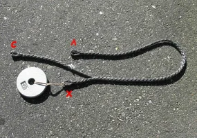
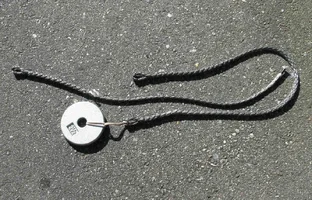
The attached photo illustrates the experimental design. The eye-and-eye sling from X to A is the "cover" of the "splice", and an entirely separate rope with the eye marked "C" is the "core."

Each experiment consisted of inserting the core to a measured depth, milking all the slack out of the splice, then mounting everything vertically. Eye A is at the top, attached to a load cell. Eye C is anchored at the bottom, while the appendix, X, hangs freely. Above the load cell is a pulley that allows the pull to be applied from the top. An experiment consists of increasing tension until the splice slips, then reading the maximum force registered by the load cell.
 

Attachments

  • 194056-Setup.webp
    194056-Setup.webp
    276.2 KB · Views: 209
This photo shows core and cover separated. The tape at the end of the core made it easy to make the splice without tools, but it was always removed before each pull test.
 

Attachments

  • 194058-Parts.webp
    194058-Parts.webp
    259.8 KB · Views: 156
In all, 27 experiments were performed in 4 series. In two of the series the appendix weight was 2.5 lbs.; in one it was 3.75 lb., and in the last it was zero. There was one anomalous reading in which an increase in bury length resulted in a decrease in splice holding force--this reading was discarded.

Over the course of the experiments, tension readings ranged from 16 lbs. to 440 lbs., and bury lengths ranged from 9.5 inches to 23 inches. A single core and cover were used for the first two series. After each test, the core was retaped and inserted back into the cover for the next test. A different pair of ropes was used for the last two series in order to allow for somewhat longer buries.

What to do with all the raw data? It was obvious just from glancing at the numbers in my notebook that the relationship between holding force and bury length was not linear: holding force grew far faster than bury length. Had I plotted bury length vs. holding force on a graph, the forces would have quickly shot up off scale. Since I had good reasons for believing the actual relationship was exponential, I decided to plot the logs of the force readings vs. bury length. This is a mathematical trick that essentially converts an exponential relationship to a linear one; if the logarithms of the forces plotted as a straight line vs. bury lengths, then the actual relationship between force and bury length is exponential.
 
And the fourth.

The data speak for themselves. All four series look linear, some almost perfectly so. The relationship between splice holding force and bury length is apparently exponential.

What does all this mean? There are two ideas here that need to be considered together. One is the length of the bury. All other things being equal, you can double the strength of a given splice in 5/16-in. Tenex by adding 3 inches to the length of the bury. If you add another 3 inches, it will double again. Conversely, reducing the bury length by 3 inches cuts the strength in half. The familiar analogy to this behavior in ordinary life is a bank account that grows by compound interest. If it takes 15 years for the account to double in size, it will double again in another 15 years. Obviously you can't start with zero dollars in the account or all the compounding will get you nowhere. It is the same with the splice--there has to be a starting force; this is the second essential idea.

Since this discussion started in the thread about loopie strength, consider the loopie. Even though you can easily pull one apart by hand, there is some friction between cover and core that constitutes the starting force. In a straight pull with the entire splice in the open, it will pull apart at a low load because the starting force is small. By putting one of the bearing points near one end of the splice, both the bearing force and the bight itself create a lot of extra holding force that wasn't there before. This force will grow along the length of the splice like the bank account growing with compound interest. But like the bank account, there is a big difference between making the deposit early in the life of the account vs. near the end. Put the bearing near the throat of the loopie and tap into the exponential growth of holding force over the whole length of the splice. Put the bearing point near the tail and miss out on the splice's ability to multiply the force.

Better yet, don't use a loopie in an open pull. This pushes it to its design limits, and even with a good understanding of the physics I have tried to present here, you are still operating in the red zone of the device. If you must use one this way, it would be prudent to use a loopie with a much longer than normal splice and to be very clear about the physics.
 

Attachments

  • 194069-chart4.webp
    194069-chart4.webp
    15.3 KB · Views: 98
Moray,

Really good work, and not being critical at all, but I believe this might be the form of a log graph to show the exponential effect.

Of course I extracted data from your graph which results in rough approximations, but I must have gotten pretty close. I raised 10 to the powers indicated on your vertical axis for each tuck length and graphed that.

This version shows the approximate doubling effect for every 3 inch increase in tuck.

3929935494_ee2a38c7c3.jpg
 
Beautiful graph, Ron. Did you make that in Excel?

For those who care but don't know, plotting the actual force values on log-scale graph paper, as Ron has done, is equivalent to plotting the logs of the values on linear graph paper, as I have done. In both cases the plotted data points should fall on a more-or-less straight line.

BTW, I noticed that the last chart didn't attach to my final post last night, as it should have, but it is there now.
 
[ QUOTE ]
Beautiful graph, Ron. Did you make that in Excel?

[/ QUOTE ]
Thanks, but you did all the work - fine job too.

Yep, I did it in Excel.

Whatever made you think that the length of tuck to strength would be exponential? I would have thought it would be linear. Surface area in contact is perhaps exponential???
 
Someone sent me a PM with this message: [ QUOTE ]
When splicing a loopie OR whoppie sling, what are your thoughts on the bury? Are the fid lengths from the manufactrers web site OK OR should we be burying more?

I do realize this test was done NOT using the proper chokering of the sling.

[/ QUOTE ]

I have not tested this, but my somewhat educated opinion is that in the chokered configuration where there is a bight in the spliced section of the sling (loopie) it should not slip. I ususally use about 1.5 fid lengths for the splice section just because it makes it easier to handle, and I always use the chokered configuration.

The whoopie is actually quite a different animal. The adjustable eye is still a true eye splice, and as long as both legs of the eye share the load almost equally, it will have a lot of holding power. If the fixed eye chokes the adjustable eye, and the splice is bent around the tree, then I would expect it to be bulletproof. Even in a straight pull, the weakest configuration, both legs of the eye would be about equally loaded and it would either hold (my guess) or not slip till very near the breaking strength of the rope. I don't worry about the whoopie, and I don't worry about the loopie, either, except in the straight pull configuration. Has anyone had one of these slip?
 
I have used tenex loopie slings for years. Once I used it in an unchokered situation, I was extremely worried, took precautions so no one would be harmed IF bad things happened. All was fine, with negligible slippage. I wouldn't make a practice of it though!

I have made loopies with 3/8 dymeema and Nick's video instructions. We use these for spider leg configuration with a crane. Chokering the adjustable eye on the limbs and the double locking brummel eye on the crane hook. They look like the day I spliced them.

I would sure like to see splicing of other rope types, I don't think I would be bold enough to attempt a double braid rope eye splice, and USE it!

This subject is WAY over my head, BUT I believe I understand what your trying to say. THANKS for enlightening us LESS informed, who knows, you may have even saved an insurance claim , OR better yet a LIFE!
 
Ahhh shoot! I just realized my graph is a line plot instead of a scatter plot. The line plot graphs data differently than the scatter plot and the scatter plot is the correct plot for this data.

I would have redone the graph, but I didn't save it. I think the difference would be that the scatter plot would probably look more linear on a log plot.
 
[ QUOTE ]
...Whatever made you think that the length of tuck to strength would be exponential? I would have thought it would be linear. Surface area in contact is perhaps exponential???

[/ QUOTE ]

You know, I don't really remember, except that even at a very early stage of experimentation it was obvious the relationship wasn't linear. I do remember the best aha! moment, which, as a fellow experimentalist, you may appreciate. I had realized that the core of a splice is more or less inert, that the cover is the active element that does the sqeezing that creates the friction to hold the thing together. One of the ropes I was working on was fairly tedious to splice over and over again, so I decided to use a wooden dowel instead of a rope core. This worked fine at very low loads, but slippage under even modest tension started ripping the dowel apart, spalling off long slivers of wood, especially at the tail end of the splice where the pressure against the wood was greatest.

The fact that the slivers would become embedded in the individual strands of the cover made them tedious to remove. This made me focus on the individual strands. As soon as I stopped thinking of the cover a unitary thing, but as a collection of individual strands, it came to me that each strand was just a rope (spirally) wrapped around a post. Aha! I knew the math describing rope friction around a post was exponential; the splice bury seemed to be a hidden case of the same thing.
 
Hi agai.n,
This series has been such a delight. But one detail: what we are talking about isn't splice strength, but splice security. I think it's an important distinction, as it is possible to have a splice (or knot) that is 100% secure, but which drastically weakens the rope.
Also, I was thinking about this thread the other day when using a Loopie to step a rather heavy wooden mast. As we've seen, the best security appears to be reached when the bearing is at the "appendix" end of the splice. But for a vertical pick like we were doing, the splice had to be on deck, which meant that if the appendix end is at the bearing, the running part is up in the air, where the weight of the rope's standing part wants to pull down and put slack into the splice. This is the reason that for years I've put the bearing at the running part end. And I did it again for this pick, and all was well. So maybe the next step is to determine how long a bury one needs to put the bearing there, and still get sufficient security. I'll be pursuing this, but if moray or anyone else is interested, stay in touch.
Fair leads,
Brion Toss
 
[ QUOTE ]
...Also, I was thinking about this thread the other day when using a Loopie to step a rather heavy wooden mast. As we've seen, the best security appears to be reached when the bearing is at the "appendix" end of the splice. But for a vertical pick like we were doing, the splice had to be on deck, which meant that if the appendix end is at the bearing, the running part is up in the air, where the weight of the rope's standing part wants to pull down and put slack into the splice. This is the reason that for years I've put the bearing at the running part end. And I did it again for this pick, and all was well...

[/ QUOTE ]

I have been trying to understand your description, but even with the photos I present here, I am still having trouble. The first photo shows the "right" way to use the vertically oriented loopie. The appendix "A" is next to the bearing shackle at the bottom. The adjusting tail of the loopie is hanging down to the left. The cover leg of the loopie (arrow) supports the entire length of the cover of the splice so it is impossible for the cover to sag downward and put slack in the splice. As load increases on the system, the splice cover sees more and more tension and locks ever tighter to the core.

3941340676_9909e6313c_o.jpg


In the next photo we see the "wrong" way to hook up the loopie. Here the bearing is at the tail-end of the splice and the appendix is at the top. At the arrow there is no tension whatever. The weight of the splice cover and appendix combined can cause the cover to slump downward introducing slack into the splice. Even if there is no slumping the splice is still very insecure because there is no reason the splice cover will ever see significant tension, and without significant tension there will be very little holding force.

3941340548_00aca02e61_o.jpg


Can you post a picture to help us understand your mast-stepping procedure? And may I ask why you need a loopie for this? Why not resplice the loopie into a fixed-length sling and eliminate all these engineering worries?
 
Hi again,
Sorry for the confusion. First, I use Loopies for masts in order to have the load come to a sling at the mast butt, instead of hanging the load on the spreaders or tangs. This also allows us to put the upper sling just above the center of gravity, so the rig isn't butt-heavy. In addition, this arrangement allows for a basket sling at the hook which makes it easier to rotate the mast to keep it in line when stepping or unstepping; a choker hitch is tough to turn. For details on this, see the "Rigger's Apprentice", page 247.
Anyway, masts come in all lengths, and a Loopie allows us to get a perfect-length sling, fast, no matter what the length.
As for your photo's, the "right" setup does make for more security -- eventually. But until the load comes on the weight of the running part definitely loosens the splice, at least in the Spectra we use. We could Rolling Hitch or the like above the splice, but it would be too easy for that hitch to get bumped, or the coil to be snagged.
The appendix, by contrast, is a short, light thing, easily hitched, and less vulnerable.
Next mast we step, I'll try to remember to photo the process.
Fair leads,
Brion Toss
 
[ QUOTE ]
...First, I use Loopies for masts in order to have the load come to a sling at the mast butt, instead of hanging the load on the spreaders or tangs...

[/ QUOTE ]
Well, this is an instance where "a picture is worth a thousand words" understates the case. Clearly I am not going to understand your setup without a picture or two.

But back to the theory.
[ QUOTE ]
...But until the load comes on the weight of the running part definitely loosens the splice, at least in the Spectra we use...

[/ QUOTE ]
OK, we don't want a loose splice--my instinct is the same as yours. To avoid a loose splice you are even willing to hook up the loopie backwards. Which, as I have shown, guarantees a loose splice, or at least one that is essentially nonfunctional. But if you were to hook up the loopie correctly, with the bearing near the appendix, what would actually happen if the splice in your Spectra was loose?

When I did this experiment a few minutes ago after forcing slack into the splice, the sling smoothly removed all the slack as load was applied. As the splice cover grew more and more taut, core was entering the cover from both ends. I was surprised to see core sliding in next to the appendix, but it appeared the adjustment was about equal at appendix and tail. The bearing point next to the appendix doesn't move at all.

After the fact, it makes perfect sense that this is how the loose splice would behave. The result is any initial looseness is harmless and self-curing. As soon as significant load is applied, the splice cover becomes taut, extra core enters the splice if it was slack to begin with, the cover grips down on the core, and everything functions as it should. None of this is true when the loopie is hooked up backwards.

You expressed interest earlier in doing some experiments of your own. I suggest a really easy one. Take your slack-prone Spectra loopie and attach it to something heavy. Hook it up correctly, make sure there is plenty of slack in the splice so we get a good test, and lift away.
 

New threads New posts

Back
Top Bottom