Decoding Patterns of Forces

*useless info*

Participating member
Location
usa
i play with numbers on computer,
to verify, decode, extend etc. understandings to functional models
>>so need for math under fire>>have model references, few benchmark numbers , flow of pattern and sense of what is right/wrong building
But, also, to pick apart things to see if that is what i've been reading into them to true that sense;
>>like trying to align my sense of things to their assured actualities
>>to then be able to read and push ahead more confidently.
The new, re-verified sense of aligning most correctly it's own driving force
>>more intentfull , purposeful, non-stalling, confident driving force flow>>clean, not necessarily racing efficiency
>>others follow more easily >>especially when working so well
i always try to find fitting in big picture, partially for cross comparison to understanding AND cross-verifying checksum
>>another way to do this is buy playing it backwards; many solutions like cheating on a maze, found in strategy alone, let alone getting to target of parity check of each some debit/credit against the other
.
Thus, so powerful to me, when find true pivotal key to many questions at once.
.
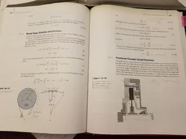
Spreadcheat purports to show Porty etc. brakeForce per half turn, frictions inside of knots etc., and controlling forces of friction hitch over host lifeline etc., also why dyneema etc. are hard to knot,
>>and makes point if same rope and round host mount( materials)
>>ONLY change in turns adjust such a friction force
>>NOT change in rope nor host mount size/friction path(for round on round)
>>larger pipe or branch host mount is for strength AND softer rope arc >>not friction increase
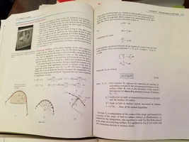
Guess friction is .25 as start point>>remember 3/5/7arcs(half circles) gives ~10/50/250x hold leverage over load as brakeForce and how pattern accelerates (to drop quick on low end, or other materials) and should be golden!
.
>>for nylon on aluminum brake (.25 CoF) for 3half circle arcs 540degrees(RT) on Porty etc.
>>hold 100# @10.55x leverage(per chart) to control load of 1055# etc.
exponential-brake-force-increases-per-added-degrees-compared-in-different-materials_3.png

.
Many, many explanations and distinct pattern here.
i've never seen a chart like this, especially of such cross comparatives of verifications and of lessons to big picture too.
Sheet is all setup to self calculate if anyone has other friction coefficients or degrees of contact questions; would be nothing to add to FREE google.sheets
.
Friction coefficients are a set few tho of accepted, engineer stated chart that is much all the same everywhere.
>>but the number can be a guess or interpolation to test!
Once again, root work: jrre.org/att_frict.pdf showing for friction brakes in rescue
 
Last edited:
That is what i felt like for years chasing this, knowing numbers seen here and there reflected what experienced with Porty, wraps on tree, knots etc. but pattern so elusive had to peel deeper to see rhythm thru math.
Hoping i've taken most of the heavy lifting out, for this defines so much of very pivotal points.
.
This is how adding an extra turn or 2 on Porty, above what already have
>>can save or ruin day, and only counting in half circles as radical exponential growth is incurred;
As real, load controlling, possibly lifesaving, better explaining and that is actuality are really watching and can help align senses to (i think) once can name and recognize to read/know better and much more re-affirmed etc.
.
Guess should save my explanation of my minimization of math to exemplify only factor that changes to change friction are the half turns, rest become constants in formula if same round materials.
.
To be clear, common Turn w/Half-Hitch has only 1 half circle, not 2 of this exponential math and intense Nip.
natural-load-powered-rope-arcs-vs-drawn-together-ends_3.png
 
Last edited:
How work got done:

capstan-frictions-enabling-force.png


2nd pic harder to see it, but tailer sitting on ground pulling rope right.
Back in the'day, would have known to look for tailer in pic
>>things like this are about all that remain of this art of power.
Perhaps not many beyond our own kind would be up to this,
>>let alone understand it in today's world!
.
3rd pic shows bollards; also non-spooling for 'endless line' like capstan
but a fixed, also non-spinning drum for brakeForce.
Simply capstan controlled pull in 'purchase' of line, Bollard the Equal/Opposite controlled pay out of line.
 
Last edited:
I think the exponential nature of the behavior has to do with the fact that the load itself is acting in two manners in the system: 1) first the loads acts is to break the static friction of the rope/porty to achieve the initial motion; 2) to provide the force to that actually determines WHAT the static friction force actually is. Generally, in a flat linear system, the weight of an object and the coefficient of static friction determine what the static friction force is that has to be overcome to move the object; and, a second (independent) force is what acts to move the object. That is not the case here. In this example, the load does both. Anytime you have a system like that, you sometimes get into a feedback type situation which results in the complicated math.
 
Last edited:
i've not been to school for this, and trying to get right base pattern thanx!
>>of course anything is going to take more to init movement than keep it going any here can say.
i actually kinda expected to see a bit of what you say from my collective understandings researching many yrs.
.
EngineeringToolBox.com is a reference standard, and the chart of CoF's appears same on it as elsewheres. But they downplay the init-effect some, and say in average it is in the calc. To me, no matter, trying to sift pattern and handful of benchmarks as relevant filed guide in head etc. can accept and go with more to bump-start than maintain model seen in all. Only the Dyneema and extended .2 to .4 nylon sling CoFs are only CoF's not on this standard list, and found them at manuf.DMM site.
.
i think rope knots/rigs are ruled by straight lines and half circle arcs. Actually, scrutinize looking for slanted lines, and assume straight happens here and there, so is slant of 0degrees. So think, cosine/sine and capstan maths rule, next would be elasticity and abrasions(not looking at taking that far).
.
For our ropes and usages, a single arc Turn is just a hook, not grip, not serious friction reduction of load force, more of a passing of reduced load, w/o grip. A Round Turn (RT) 3arcs turn to me is real working man alternative and power rating with the grip. And whose friction reductions would now show as grip on host for 2 utility functions from same property.
.
This view of sheet, takes the 10.5 force reduction of RT of nylon on aluminum pipe att_frict.pdf shows as .25CoF as a benchmark real working hard working/usable mechanic, and compares in various material CoF's as a pattern to sift and understand more by.
.
Re-affirming so concretely, how much more 'frictive'(knudeKnoggin again) hemp was/is (shows compared to wood) and how slippery Dyneema/UHMWPE (stronger than Kevlar) is almost slippery/hard to knot as Teflon! Spreadsheets can be jsut a flurry of a bunch of numbers, until can float some patterns out!
.
round-turn-exponential-brake-force--compared-in-different-materials.png
.
Legend has it in our lore, can be injured or killed from too many wraps/half arcs, by employing too much BrakeForce with these methods. RiP pioneer/scientist/contributor/benefactor Peter S. Donzelli . So, any amount of half circel arcs can be not enough or too much, but in our ropes going from 3arcs to 5arcs and on is a big change, to be heavily 'weighed' i'd think.
.
i always tried to look at turns and describe knots and mechanix as definitive. This has re-affirmed that so much as to start over and show knotting start, really focusing on counting the half arcs(and smoothing slants) to l-earn and define.
 
Last edited:
A simple way to look at it like this. Imagine increasing the load. This will increase the force of the rope against the pipe, which will in turn increase the static friction force. It will also flatten the rope more creating more surface area contact, which in turn will increase the actual coefficient of static friction itself. BUT, at the same time, the very load which is doing all of this is also trying to break the rope free. This interaction can be described by a mathematical function, at which point we call in Russell Crow. So we have the force acting on the system, which is one variable; second we have the force acting to create the static friction, which is another variable; thirdly, we have a flattening phenomenon which is yet another variable. BUT, in this case, each of the three variables is dependent on THE SAME THING - the load. One variable acts to move the rope, and the other two act to keep the rope stationary. This tug-of-war in the math can result in some tricky equations. But one thing is for sure, anytime you have the same input (the load) acting in multiple variables in the equation, you usually get some math that is not linear. At the very least, I would expect it to be a x-square relationship, but it appears mother nature intervened and brought in Euler's number.

Hey, I was just curious if that spreadsheet is actual measured numbers, or if it was calculated? If the latter, then you can get into the sheet and find the actual equations.
 
Wow, thanx!
These 'extras' would be more to exponent of loading/'aggravated to flattening etc.
>>am still thinking that capstan equation shows base pattern, to just align to proper benchmarks in actual scenario. And to these models, a'lil extra help is just a safer model that bluffs low, not high.
.
Spreadsheet is calculated from base capstan formula found all around on engineer sites and highlighted in att_frict.pdf. Then checked calls against same. i can send you google.sheets link when get home, there is 'flat' CoF's, then sheet for 'radial' CoF's shown above and RT sheet shown here; all locked. But also play area/unlocked sheet can alter half circle/radian arcs or CoF's and hit ENTER and sheet re-calcs. If someone else wants to peek or play(not like that Rico) with sheet, can PM me, just don't want to publicly post open sheet on my acct. Free google docs with google drive, including excel type spreadsheets (and form maker that fills spreadsheet from football pool etc. ) are FREE awesome tools!
 
Thanks for the big reminder take away that bollard friction generation/multiplication is not linear with wraps; it's exponential. Explains the huge jumps on the BMS belay spool. I'd completely blanked on the actual bollard equation lately and started thinking it was linear. Kudos.

Years ago on a project a small line drove a mechanism and the change from bushing pulleys to bearing pulleys made/broke the system because the friction cascaded; the first bit affected the next and tension skyrocketed after about 5 stages. Same idea, force makes normal force makes more force makes more normal force makes more force etc cascading. It was really eye opening at the time.
 
per *useless info*
Spreadcheat purports to show Porty etc. brakeForce per half turn, frictions inside of knots
Except that this approach fails when applied to non-jamming knots such as the Zeppelin bend. This 'bend' remains jam resistant right up to its MBS yield point.
I would also comment that in all of the primary Bowlines based on single or double helical nipping loop, the clamping power of the nipping loop overrides any potential capstan effect of the collar performing a U turn around the Standing Part (SPart).
Evidence of this can be found in the collar of a simple (#1010) Bowline while under load - it can be moved - which indicates that force is not evenly propagated across al rope segments in a knot.

So in my view, looking at 'turns' inside a knot structure is not providing a holistic interpretation of how force is propagated in and around the knot core.
 
Wow, so sorry; got so buried in drawing for Zeppelin in other thread and went on and forgot about this..
.
Zeppelin:
Tried to show in that thread that Zepp primary 'hooks' (Spart + 1st arc each) as most hard tensioned parts/surfaces of all but binding knots. Therefore most be defining. The 'boxcars' of the hooks are side by side in Zepp, not into each other as in Rigger's, Alpine resolve Rigger's fault with counter torque cow flow and open/weaker sides of hooks line up LINK
.
Bowline:
Different kind of hook flow lengthwise HH (right angle grab of collar tails as host for lengthwise pull on them) of hook in and hook out of/in electric schematic sense pass thru like bend/not termination like hitch that is always different.
i consider nipping loop as part of capstan math of the traced force path
>>but more so in Sheep & Sheet where HH is flatter
>>with lower force in and out of this HH device piece etc.
>>capstan math effects to me is 'radial friction' between mating surfaces, this would seem inescapable, perhaps lessened by lower CoF than alum/nylon, and tight bight effects(?)
>>But have the primary 'hook' of I Beam of support and 1st arc feeding in straight line to restriction against a LINEAR pull as force change here. The hook to hook in/out imagery is a straightline vs. full force trace around the turn(w/linear force..). More of a lengthwise than right angle 'Killick', changes everything.
.
i think we can find the diploid of 'Nipping Loop' and 'Collar' tensions as allowing/disallowing switch by how Collar enforces the dis-position of the Nipping Loop and how that geometry carries the force ported thru.
.
Simplest Sister would be Sheet Bend with diverted geometry and forces but that part of rope doesn't sit same.
Closer tho find Sheep Shank w/SParts thru the loose eyes(really only need 1 to mimic tight collar)
>>Have found if shorten 'Collar Legs' to close enough that rope stiffness can lightly leverage to hold rotation of HH to more of an inline pass of force thru linked hooks like lengthwise HH like Killik vs. more towards right angle grab of Slingstone type Kelleg(at work can't chase all the names and numbers..)
1ST HOOK in right angle grab on host is host, but in lengthwise pull is to other rope part offering a more linear path to the linear force, than the right angle bend to side around host.
>>But when the 'top' of Collar slaps Spart just so, in a leveraged position per stiffness of rope;
the Nipping Loop is looser
.
Like position of Clove X crossing low, med, high like in HH positions
More like getting the X crossing of Sailor Hitch totally on top/opposite the pull (as Roo shows, but i like using the Bitter End as crank to secure same position)
>>rest of 'carriage' of rope relaxes considerably. The same knot geometry, in different geometric orientation to the force pull to single point(s) giving different effects (vs'glowing radius' of even force flow loading in binding knots ).
.
Similarly, can see dual pulled Clove ends
.
Am at work, writing this in pieces, sorry. But dare say the 'flippy' loop noted in Bowline would be less so with looser collar, like in Sheep Shank. Only in Bowline use the Standing Part to prevent Sheepy roll out of 'collar'..
.
In Bowline the 'Nipping Loop' must be so close to 'Collar' per stiffness of the line to enforce HH/'Nipping Loop' position more to 2 interlaced hooks continuous flow of force like HH in Killick, to likewise grab the 'Legs'(?) of 'Collar' like HH does spar. 1 side of which is (almost)not firm.
Different kind of primary hook imagery in right angle vs. lengthwise 'Killick" to me
 
Last edited:
Zeppelin:
Tried to show in that thread that Zepp primary 'hooks' (Spart + 1st arc each) as most hard tensioned parts/surfaces of all but binding knots. Therefore most be defining. The 'boxcars' of the hooks are side by side in Zepp, not into each other as in Rigger's, Alpine resolve Rigger's fault with counter torque cow flow and open/weaker sides of hooks line up LINK

The reason why the Zeppelin bend is jam resistant is complex but can be understood in terms of a 'toggle axis'. See my paper on the Zeppelin bend here:
Link: http://www.paci.com.au/knots.php (at #4 in the table)
Fundamentally, the Zeppelin bend is constructed from 2 superposed loops of opposite chirality.
In comparison, #1425A Riggers bend is constructed from 2 inter-linked loops of the same chirality.

In the Zeppelin bend, both SParts perform a U turn around their respective 'tails' - which has the effect of trapping and crushing those tails (which creates a toggle axis). Under load, we can see the knot 'pivoting' about this axis. Force transfer to each respective collar is retarded by the toggle axis.

...

The simple #1010 Bowline works in a completely different way. I would also comment that a #1431 Sheet bend is not a good analogue for a #1010 Bowline - they work differently.
The #1010 Bowline is a fixed eye knot and force enters the core via 3 conduits.
The Sheet bend is not a fixed eye knot - it is a 'bend' (obviously). Force enters the core of all bends via 2 conduits set at 180 degrees in opposition.
Also, a Sheet bend doesn't have a 'nipping loop'. A nipping loop is loaded at both ends, is TIB, has a defined chirality and is based on a simple helix (chirality is an inherent property of all 'loops').
For a deep dive into 'Bowlines' its the paper at #2 in the above link.
 
Spreadsheet is calculated from base capstan formula found all around on engineer sites and highlighted in att_frict.pdf. Then checked calls against same. i can send you google.sheets link when get home, there is 'flat' CoF's, then sheet for 'radial' CoF's shown above and RT sheet shown here; all locked. But also play area/unlocked sheet can alter half circle/radian arcs or CoF's and hit ENTER and sheet re-calcs

Thanks for posting the link to the article. A few years ago when there was a discussion here about rope tension in an SRT access line that was threaded over multiple branches I had started making a spreadsheet to estimate tension. Since the project was for my own enrichment I didn't research online how to calculate it but rather used a machine design textbook I had on hand to see what I could come up with with that first before looking to see how others did it. After a couple false starts I settled on equations for a band brake/clutch which interestingly in the article that's where they say the capstan equation comes from. Anyway, while being in the right ballpark, the equations in that particular book had some variables that were proving difficult for me to estimate.

Shortly after I had happened to run into a professor I know at the store and explained the trouble in the calculations. He chuckled and said the approach and governing equation was correct but needed a different derivation of the equation that didn't require the variables I was struggling with. He pointed me to a different book and sure enough, it's the same T2=T1*e^mu*beta equation used in the article you posted. It helps to know people that have the answers :D

Anyway, my laptop crashed before finishing the spreadsheet and ran out of gas on the project but the plan was to use the same approach as they did in the article i.e. estimate the total radians of contact over multiple branches in order to provide an intuition for the forces in the rope/tree. I say "intuition" because exact calculations aren't usually necessary or possible. It's the general idea and pattern of forces the we take with us in day to day work.
 

Attachments

  • 20191020_090358.webp
    20191020_090358.webp
    227.2 KB · Views: 8
  • 20191020_090404.webp
    20191020_090404.webp
    321.6 KB · Views: 7
A simple way to look at it like this. Imagine increasing the load. This will increase the force of the rope against the pipe, which will in turn increase the static friction force. It will also flatten the rope more creating more surface area contact, which in turn will increase the actual coefficient of static friction itself. BUT, at the same time, the very load which is doing all of this is also trying to break the rope free. This interaction can be described by a mathematical function, at which point we call in Russell Crow. So we have the force acting on the system, which is one variable; second we have the force acting to create the static friction, which is another variable; thirdly, we have a flattening phenomenon which is yet another variable.

It seems counterintuitive but the contact area isn't actually factored into the friction force calculation and explained in the article.
 
I say "intuition" because exact calculations aren't usually necessary or possible. It's the general idea and pattern of forces the we take with us in day to day work.

It seems counterintuitive but the contact area isn't actually factored into the friction force calculation and explained in the article.
.
Nice, thanx agent_smith especially for 'new' term 'toggle axis' as descriptor had none there; but otherwise we may say different dialect for many of the same things. Zepps are not tangled, are side by side etc. i keep trying to imagine stiffened 'bar' of Zepp and how stiffened as a bitt in horses mouth but Toggle Axis is fair-er. i would say tho that each hook goes around the pair the pair of ends, that form this axis.
.
i think that both Sheet Bend and Bowline have Half Hitches. Sheet Bend is of the termination type, and Bowline of the continuous lengthwise / Killick type(once again electrical flow imagery). You can also have a Killick pull at right angle, but handles more like Sheet than Killick forces. i see the continuous as dual/back to back termination HH's; just sharing the same termination point ; that legs serve in and out of. Not sure on that one, but constantly has nagged at me why both are called Half-Hitches , and this is one theory of what was oh so obvious to those eyes and not mine.
.
If the Collar stiffness/tightness is too loose in Bowline the 'Nipping Loop' is tight(and vice/versa); as is not held in more right angle architecture. To finally prove to self used Sheep Shank(with Nipping Loop each end) with reeved/threaded ends to mimic Bowline, 1 tight, 1 loose. Guarantees same load and materials, don't really have to reeve the loose end to see effect that is enforced by this lever of the HH laying flat/tight/when collar loose or more 3D/right angle sit of HH when collar acts as lever to hold this 'shelf'; rather than flat teardrop down wall geometry. Collar in Sheet Bend doesn't do this as termination, not flow thru HH. In all examples tried of this tho: the inline parts of force flow are tight, not the right angle; stiffness/enght of collar legs in Bowline to enforce the right angle position of HH /Nipping Loop seems to be the game changer switch. If one end of Sheep Shank is not reeved/threaded to Bowline look, the un-threaded woulda-been-collar itself sits slack at right angle/not inline with force flow(reeved doesn't exemplify this trade off visually, but mechanically is same). 1st HH (towards SPart) in Water Bowline with loose eye flatter/tighter HH, 2nd HH usually right angle shelf HH that is looser as not inline with line of force(would have to be spaced far from 1st to flatten/tighten HH).

Note that a right angle pull on Killick, primary hook is around host as straightest line path. But lengthwise pull on same lacing, the first pull is against the opposing leg of HH as straightest line that rope tension will try to assume, like better electrical path flow among alternate routes. If have 'Simpler Sister' model of just running Bowline around spar, right angle pull to host is same as shown, but lengthwise pull under hard pull many times rope trys to assimilate the best it can this straight line from pull to 1st arc as slanted across host mount. Directional modifier of preceding with HH corrects the condition, may take 2. i think straight line is the primary force path sought by force, angled support mostly used as make do same job at lower efficiency to your cos(cause) and having to withstand the sin of side forces at the same time. Tension pull of rope will try to pull equal/opposites inline (whereby compression working in same scenario would try to push E/O points further apart.. ) .
.
Both papers very nice works/contributions, somehow had missed the Zeppelin before, thanx!
.
i try to sight out in looking at these things:
SPart as input of force into knot(except in binding knots) is most definitive as greatest force AND hardest surface. This primary straight line is as IBeam of support backbone, should be straight/true as possible for most strength efficiency; 1st arc induces primary force reduction. So primary hook is most definitive pipeline of force and direction as serve and grab of greatest forces in this knot microcosm (and hard nipping surfaces besides any other host). Bends have 2 SParts / coupled IBeams as a flow thru point, Hitches and knots like Bowline etc. are force flow termination points of 1 SPart/IBeam serving forces into knot internals.
.
 
My take on linear force line trying to prevail as support against linear force, so then this force line carries most loaded forces. Forces not on this line are lesser.
.
Bowline Nipping Loop only loose when collar taut enough to hold loop closer to right angle, out of the most direct and intense force line. In this position , force line continues straight to other leg of HH , loop is only consequence of the inline forces.
But, find if collar is loose, Nipping Loop pulls inline flatter to force line and is tighter as force must fully pass thru to get to other leg and collar tries to sheep/roll out.
In simpler model of force line mechanix, describe Square Knot correct as binder, built in quick release as is just 2 slipped hooks
>>but wrong as bend cuz the lock is not on the inline power side(against host/parcel)
>>by removing ROUND host/parcel to Nip on the force line as pull straight , crossing on SParts is a slip, not lock(until Sheet Bend crosses 1 leg over to the power side, to hold power by bringing the load force into the lock on 1 leg to passive hook mount, both legs locked position doesn't hold position well in round but well in opposing geometry of flat, or even some mixes )
To me this is like locking with the lesser resistive force cotter key, not the main power player hitch pin
>>just not the same bet, using the secondary nip only in bend vs. primary force nip backed by keeper of secondary force nip in Binding..
(line of force rules, is always main power source for rest of passive responding chain/system)
.
Capstan math is based on line tension as multiplier, so will be less, when not on direct force line; when off to side/less direct feed of force into it.
.
Sheet Bend has shrinking HH of termination type not pass thru. Without other leg of pull on HH can't warp to right angle even with looser collar. Always look for this flatter loop to be tight.
.
Sheepshank could roll out of heftier , more frictive hemp, so trust in slicker synthetics only as mechanix model in risks of real loads in working world. Favour Alpine Butterfly for shortening line or isolating faulted line part instead of Sheepshank. i think i've noted, but don't use enough to prove beyond play; that Sheepshank is more stable if the loose 'would be collars' are not to same side, kinda start from more self stabilizing /countering Cow, rather than continuous Clove as one view of this.

linear-pull-forces-working-in-straight-line -.png

i think pure inline imagery simply works for the forces faced are linear
i think the primary hook imagery works cuz
>>Standing Part is most loaded, IBeam backbone of loaded rope parts
>>1st arc is primary reduction of forces.
Therefore: primary hook of Spart + 1st arc define by being most force loaded parts of rope as points past are after first arc friction reductions; so must be lessor.
>>so most powerful , dictating also force input
>> hard surfaces to nip securely against are very important to knots; the most loaded primary hook therefore provides also the hardest rope part nipping surface to rest of rope parts. Bowline can create and hold this nipping surface for use, so is a stand-alone KNOT , Clove or Sheet Bend need 3rd party hard host to nip against as termination endpoint HITCH (Clove) or force pass thru BEND(Sheet Bend 2 SParts or more) that need 3rd party to provide the hard nipping surface, so are not called KNOTS (mostly). Once again all to an electrical type force path imagery. BINDING KNOTS need host mount too, but are different in the force comes from inside to power knot forces . Rest have force served from outside knot/connection into knot so not all rope parts as evenly loaded as in binding knots..
 
Last edited:
Other knots too, can vary in strength and security per the position of crossings etc. varying the forces ported thru the very same lacing. Thus not all Cloves are equal, any more than all nail positions /or load pulls on a given nail position. Or current run wrong thru a circuit. A tool as any other needs to be deployed right to get best predictable performance at lowest risk with lowest materials and time etc. Rope is round to give predictable/same performance at different angles(geometry again), so favored even tho some usages would be better in equivalent strength flat rope/webbing. Round Rope has more varying usages, knotting, storage, turns around trees etc. that makes predictable round the preferred profile. Some things poor in round are capital few usages in flat profile so that this 'opposite geometry' finds more strength (in Overhand knots and Whatknot )that shown very disfavorable in round.
.
Rope(as flexible device) is simply magical pliable putty that can quickly make/unmake these tools/machines in.
>>but such machines no less ruled by same mechanix as rigid tools, even tho didn't spend hours carving, cutting, pounding, heating, drilling to make then unmake machines between tasks.
>>flexible device based machines are also subject to same geometry rules as rigid based counterparts*
Rigging, climbing, sailing etc. exemplify this greatly daily in application and control of forces and speed of deployment from task to task with same miracle rope device that folks have used since before there were words or lever i think. Knotting perhaps most native 1st tool outside of self, 1st engineering of a series of steps in order or fails(outside self) , 1st connection of amounts and/or properties to greater combination (outside self) etc.
.
Thus, a Sailor, Clove etc. are like any other tool that can be used more (or less) optimally to/against target. The differing radial/capstan positions of pressure vs load position(s) are critical to this view(same radial forces all around circumference are found in Binding Knots only), and find most nip on side of host mount/opposing pull load(usually 'top' with load pull 'down') ; top is where the primary 'hook' (i try to show in other pix)/pull seats into host mount the hardest, most securely as ready force to tap into. Sailor's Hitch very unique knot with purposeful top nip usage probably exemplifies this the best.
.
Roo's Notable Knot Index shows Sailor as a proper top nipper
sh1.gif

.
i show Sailor's Hitch top nipper with the Bitter End pulled up for i usually use this end as a positioning handle to align crossings for the top nip, and the tail remains standing many times. (actually i use slip or mod to have better handle for this action). Sailor Hitch top nip to me makes rope lay were we'd make it bed on support mount for best performance if the generic round had specialty troughs made to hold rope alignment proper to this target. Sailor's Hitch simply seems to lend this guiding architecture to the generic cylinder, to afford this prize positioning of aligned parts and their forces! In lacing 1 end around to make Pile or Sailor's, i always make the Crossed Turn side first across SPart, so fake like making Clove except last tuck, go around SPart as if making Muenter instead, then back up around top to fold down and bury under the X crossing(mostly like RED low crossing Sailor below), then use end as handle to position that crossing on top (like GREEN Sailor's below).

top-most opposing-nip-can-give-both-greater-security-and-strength.png
.
1st time i played with Sailor's Hitch on rail i just instinctively pulled that tail as handle to seat the top nip, like something i'd seen in old B&W movie(?) seems to flash by. i very purposefully raise the SPart to make sure not starting with side pressure from Backhand Turn portion against it some first tho,sometimes kinda both at same time. Then lay back down to load. Very little force from SPart goes past this point into rest of knot 'carriage'. Making the weight of the line alone, assisted by trace frictions, more than a nominal player in ratio. Sailor's Hitch greatly re-affirmed my primary hook imagery like no other, even tho force line breaks imagery some as hard force doesn't complete the last 90degrees to weaker side of hook as virtually any other lacing does!
.
Sailor's Hitch is a great hitch, Sailor's Gripping Hitch a great friction hitch, even competing with Icicle friction Hitch. Icicle Hitch was initially shown in 1990s w/world acclaim as to hold on a receding taper (if slowly and properly , carefully loaded). (ABoK actually shows hitches on taper after drying with ashes, perhaps wrapping with rubber inner tube and last hold after many HH's is nail etc. or even 3 strand end unraveled and taped down!! HH's are that good!!!) Icicle is like Pile Hitch with extra turns. Pile/Icicle should be pulled from the leg feeding to Crossing Turn side (where would add extra turns to make Icicle) as stronger than if using the leg to Backhand Turn side that then puts pressure sideways against SPart to deform it more. Then any side force should draw SPart over Bitter End as Icicle does.
.
Sailor's Hitch not seen too much in tree work as the amount of access needed to mount/dismount from host load or support. In lowering loads would have to untie from bottom side. On a support need generous all around access for few turns and lacing. (side note: ABoK repeatedly notes in contrast, that Backhand Turn very different than other bases in that only need 1 pass around host for dual/double bearing grab like round sling choker)
.
Sailor not recommended for small host mounts either, as top nip does carry from just top point concentrating all of load into short section of line, rather than sharing same around limb(thus would also be poor choice if any binding effect was needed). Ashley in ABoK notes on small host mounts a Round Turn rather than single Turn can be better to share out the wear of the grip. i prefer mounts at least 6x rope diameter. Conversely, Pile Hitch construction is GREAT even when rope larger than host mount , like a shipping dock hook to hold, but of course some weakening deformity. Have always had special amazement of friction hitches, Trucker's even more so than other knots, but Bag and Sailor's too, even if not tree work primaries.
.
Another point Ashley makes several times to size of host mounts and securing pinch is how much more a slip or spacer to serve Bitter End more into greater nip pressure zones can give significant increase in securing nip. This again reeks totally of geometry. Points like this are where i read ABoK as numbered lessons on mechanix of all knot potentials, that the given knot is just an example of! Totally different read of cross comparisons rather than how many can ya tie (and know less of)!
.
Many things examined here, that can apply to each knot made; even if not purposefully invoked. Purposefully invoked and eagerly watched has revealed much like tuning race car to extremes just to have to go back to find pivotal basics!


*except flexibles only resist on inline axis and in the tension/pull direction of that inline axis;
(thus side forces will always try to correct to alignment and pull to pure inline with equal/opposites as tension based force promised in rope vs. compression would steer more out of line with side force like footcam w/o chest roller)
>>also need RIGID(ity) counterpart from environment as outer framework/anchor etc.
 

New threads New posts

Kask Stihl NORTHEASTERN Arborists Wesspur TreeStuff.com Teufelberger Westminster X-Rigging Teufelberger
Back
Top Bottom