Remote controlled 72’ tracked lift

CanaryBoss

Branched out member
Location
Jacksonville
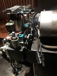
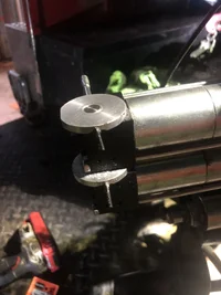
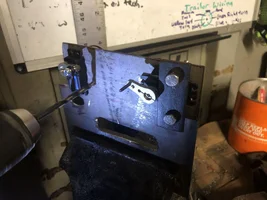
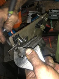
So I got tired of the ever breaking wires remote harnes for the drive controller. I made mine remote controlled with servo motors. Anyone ever tried this or have any questions or comments. It seems to work well and cost WAY LESS that replacing tracked lift parts and waiting for shipping.
 

Attachments

  • 2777CC93-D4D6-4227-A381-2BF3D0D26A68.webp
    2777CC93-D4D6-4227-A381-2BF3D0D26A68.webp
    314.1 KB · Views: 61
I just finished adding radio remote controller on my track stump grinder. It controls all track movement with 3 different speed. it also controls the swinging and up n down of the cutting head. works great!
 
Canapyboss, could u share with us where u get all ur components and boards and a brief description how u made it for ur remote? I’m very proficient with electronic circuitry and an a HAM. I did not make mine from scratch (components or individual board) since I dont know where to get them. I use a ready made remote control made for Carlton stump grinder. I’d really like to learn to build one from scratch in case I can no longer get the starting remote from the guy in Michigan. He can b very hard to deal with.
 
Last edited:
I can share the info with you. I’m no expert. Just had a customer who owned a hobby shop that I happened to talk to around the time when I was getting so freaking fed up with these drive controllers always breaking. Hindsight being 2020, I may have done it a little different.
 
I made my servos move the manual controls, I probable should have just had my reliever power the magnets in my valve bodies. That would be a lot less moving parts for sure. Don’t know if it would work tho
 
So if you look at the manual controls on the back of your machine, that I’ll call “disks”, there is a three wire, two screw pressure sensor that reads when the disks are manually turned and engages a throttle solenoid. I tapped holes on the opposite side of them with a 3mm tap. Then I inserted turnbuckle style bolts into them. They allow my servos to connect with the disks.
 

Attachments

  • B5C0C8E8-160A-423A-B4DF-336A53106080.webp
    B5C0C8E8-160A-423A-B4DF-336A53106080.webp
    262.5 KB · Views: 20
I mention the three wire sensors cause I originally thought they were the engagement point for the computer to engage the valve body, but they are not. I believe there are magnet powered switches below that actually handle the business end of the deal. If I would have figured that out before, I may have just tried pushing power into them instead of building a totally separate mechanical device. I don’t know what voltage they run on and since transmitter are usually no more that 8 volts it may require some kind of step-up to be able to power it. Am I making sense?
 
After we treaded the rods into the disks, We built a mounting plate that is basically just a piece of sheet metal with cutouts to hold the servos. It goes in between the valve body and the mounting bracket on the machine. It’s very straightforward.
 

Attachments

  • E5B5271F-C07D-4304-A7FD-F120955CD309.webp
    E5B5271F-C07D-4304-A7FD-F120955CD309.webp
    272.4 KB · Views: 15
  • E3F6473E-ADA0-4E5A-B281-ED35122A1141.webp
    E3F6473E-ADA0-4E5A-B281-ED35122A1141.webp
    330.1 KB · Views: 13
thanks for taking time to write up. Your learning will be very valuable to people who are going through the same process in the future. Also, I like to write up what I did just to document it for my own use too because I normally have no idea how I did thing 10 years ago. What I’m more interested is where you or the shop sourced all the component boards and materials
 
The servos can be purchased on Amazon. The company that I purchased my stuff from is called hurricane hobbies. They’re located in Mandarin in Jacksonville Florida. If you were to contact the shops owner his name is Ron. He could probably just provide you with the exact same list of materials that I purchased. I did buy the servos from him
 

New threads New posts

Back
Top Bottom